- Topic ID: id_17423076
- Version: 3.0
- Date: Apr 22, 2019 12:56:33 AM
Merc40 DAS-Detector Assembly Replacement Procedure
Prerequisites
Overview
This procedure describes how to replace Merc40 DAS-Detector assembly.
1 System Preparation
Procedure
- At the console start the [FRDM Wizard] from the Common Service
Desktop Replacement tab. Figure 1 shows the main screen.
Figure 1. Process Tool
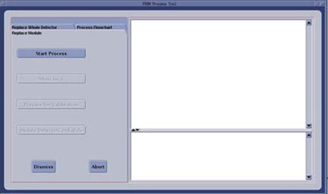
- Select the [Replace Whole Detector] tab and then [Start Process]. This will set up the system software to prepare for a Detector replacement. The physical replacement can now be performed.
- Move the table full back and its lowest position.
- (For Performix 40 Plus_LB Tube Only) Stop the X-ray tube rotor by [LB Tube Rotor Control] in the Common Service Desktop Diagnostics tab. Refer to Liquid Bearing Tube Rotor stop procedure for details.
- Remove the right side gantry cover and disable Axial Drive and HVDC from the service switch panel.
- Position the gantry at 12 o’clock.
- Turn off the 120VAC switch on the service switch panel.
- Remove all gantry covers except rear cover. Refer to Replacement → Gantry → Enclosure → (Cover Removal Procedures).
- Slide out the gantry rear cover.
2 SCORP Removal
Procedure
- Disconnect four front cables and one rear cable from SCORP Assembly.
- Detach and remove cable clamp from top of SCORP Assembly with a 3mm Allen Wrench.
- Move cable bundle away from SCORP Assembly in order to avoid damage during SCORP Assembly removal / install process.
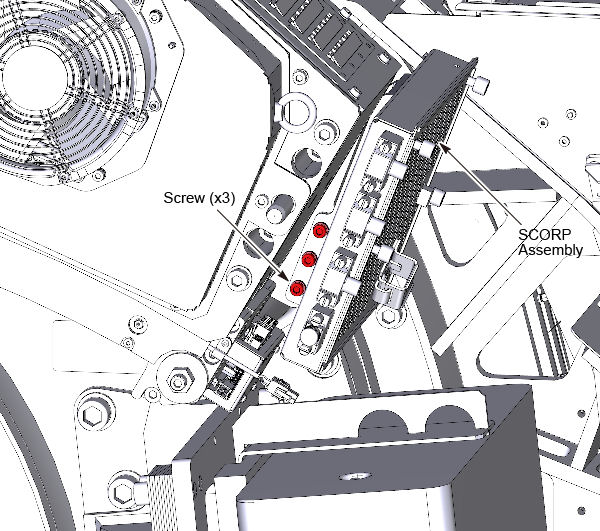
- Remove three M6 mounting screws from front of gantry with a
5mm hex bit socket drive and 12 inch extension (See Figure 2).
Figure 2. SCORP Assembly Mounting Screws
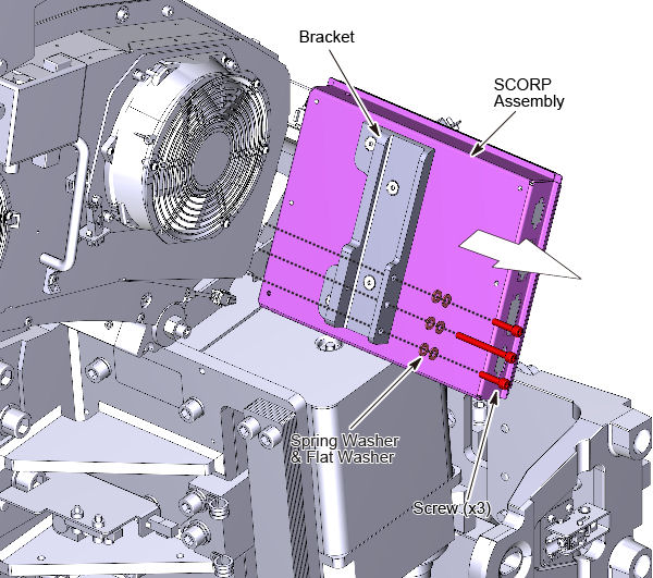
- Remove SCORP Assembly with bracket from gantry.
Figure 3. SCORP Assembly Removal
3 DAS Power Supply Removal
Procedure
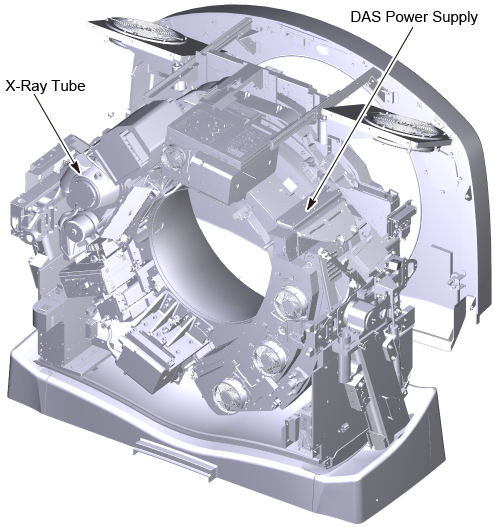
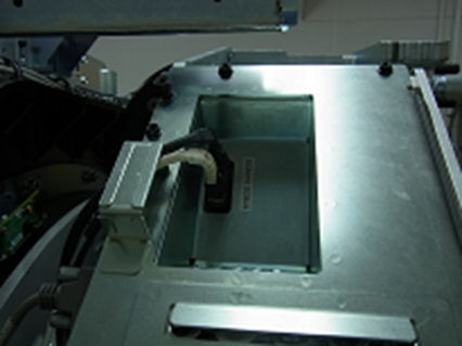
- Position the DAS power supply at 3 o’clock.
Figure 4. Position of DAS Power Supply
 danger
- Remove the Power supply input and output cables on the front
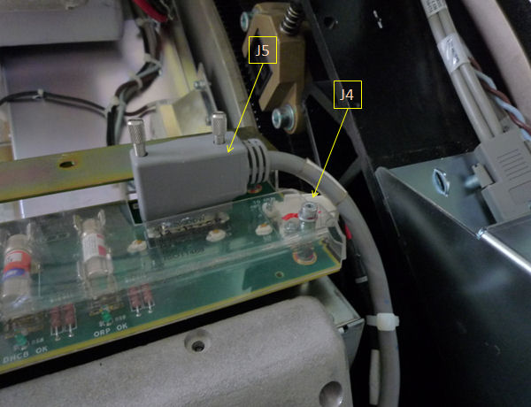
and rear of the supply as shown in Figure 5 and Figure 6. Tie-wraps
for the front cable support need to be removed as shown. Make note
of any other tywraps removed during supply removal for reinstallation
later. Also remove cable clamps attaching the output cables to the
power supply assembly.
Figure 5. Example 48V Power Supply Front View
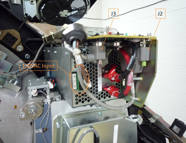
Figure 6. Example 48V Power Supply Side View
- Disconnect the AC input cables from the terminal strip on the front of the power supply.
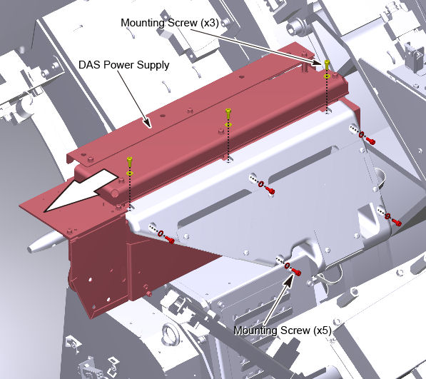
- Remove the 8 mounting screws attaching the power supply assembly
to the cast frame and slide the supply out the front of the gantry.
Figure 7. DAS Power Supply Removal
4 DAS Cables Removal
Procedure
- Position the detector at 12 o'clock and lock gantry rotation.
- Cover the Tube Collimator port to protect it against dropped tools or screws. (Cloth or any other available item)
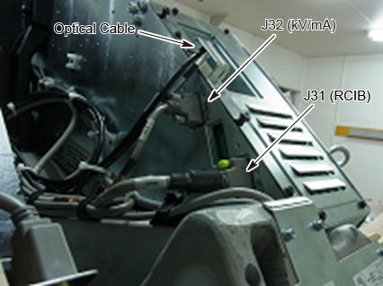
- Disconnect optical cables from CDCB.
Figure 8. Optical Cables
- Disconnect J31 and J32 from DAS backplane.
Figure 9. DAS Backplane (Low Channel Side)
- Disconnect J51 from DAS backplane.
Figure 10. DAS Backplane (High Channel Side)
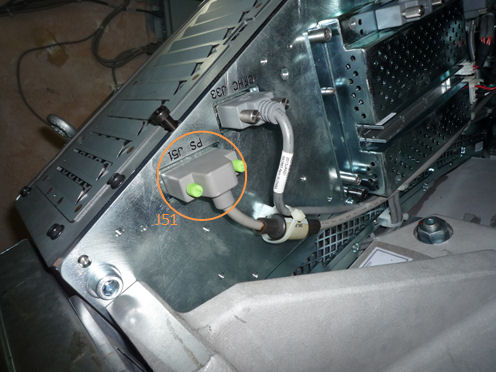
- Cut any tie-wraps fixed the J51 connector cable to the DAS assembly, and free the cable from the DAS assembly.
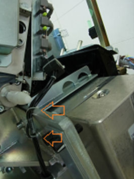
- Cut tie-wraps which are fixing LASER harness.
Figure 11. Fixing Tie-Wraps for Laser Harness
5 Balance Weight Removal
Procedure
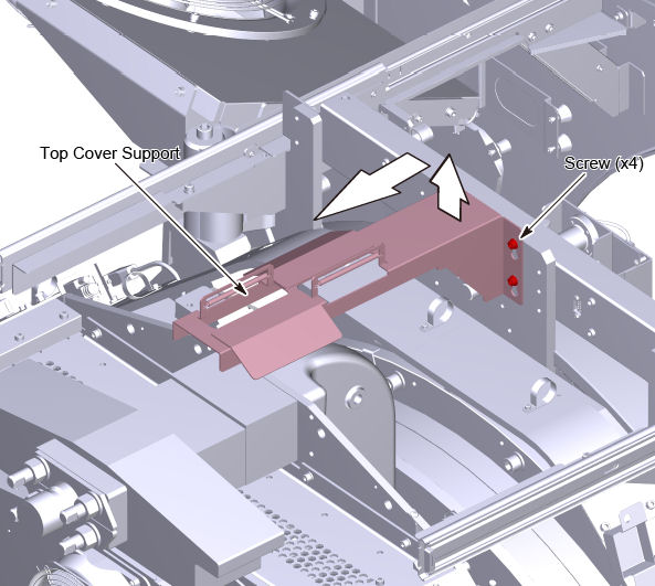
- Remove the top cover support. Use a marker to draw a line on
the top cover mount joint such that it can easily be put back in place
later.
Figure 12. Top Cover Support
- Remove the gantry balance weights over top of the detector chassis.
Keep them in order to put them back in the exact same order when done.
Figure 13. Gantry Balance Weights
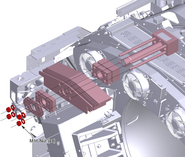
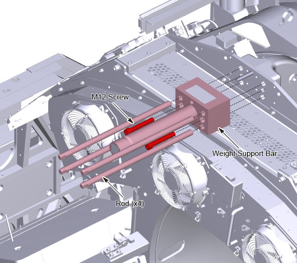
- Remove four rods and two M12 screws, and remove the weight
support bar.
Figure 14. Weight Support Bar Removal
6 DAS-Detector Assembly Removal
Procedure
- warning
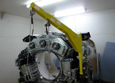
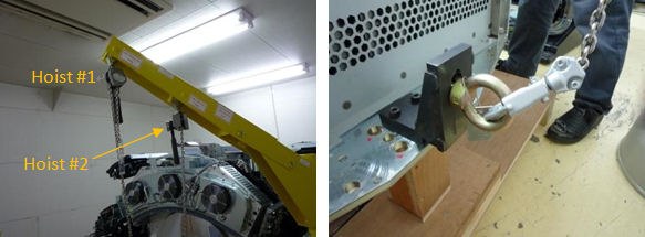
- Install the gantry lift fixture with detector extension arm
and the two chain hoists as shown in the Figure 15.
Figure 15. Gantry Lift Fixture with Detector Extension Arm
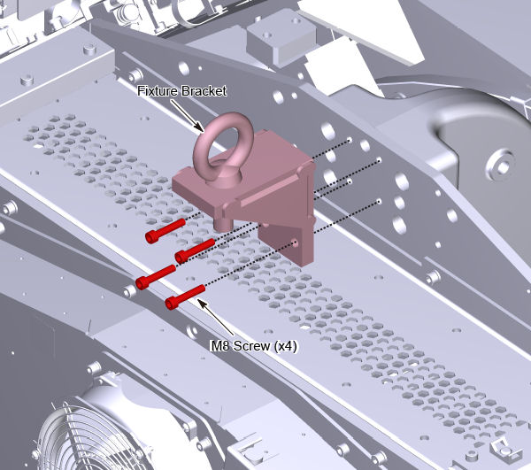
- Install the lifting hook to the top of DAS plate with four M8
screws (Torque: see Table 7). Turn the eyebolt to the direction as shown
in Figure 16 and fix the nut.
Figure 16. Lifting Hook
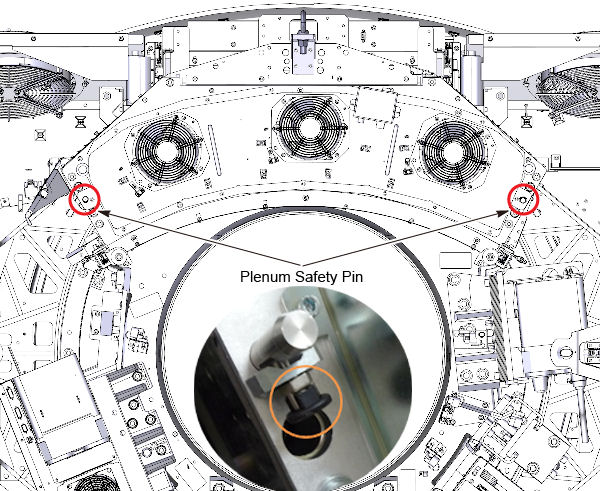
- Disengage safety pins on both sides of plenum.
Figure 17. Plenum Safety Pins
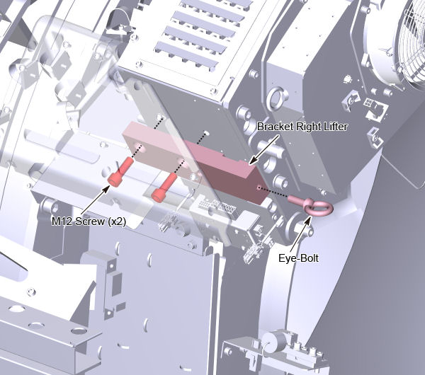
- Install the lifting bracket to both sides of the DAS - Detector
assembly with two M12 screws (Torque: see Table 8).
Figure 18. Lifting Bracket Left
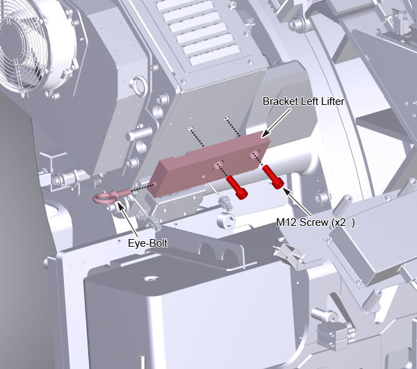
Figure 19. Lifting Bracket Right
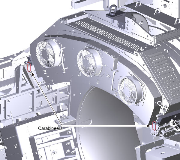
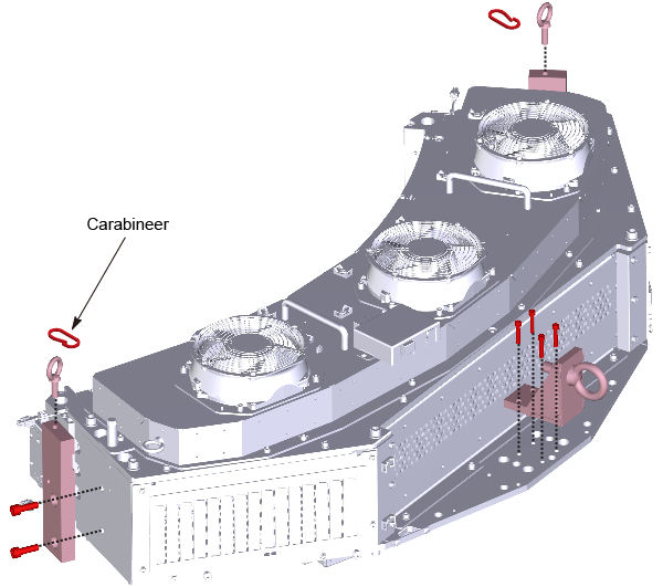
- Install eyebolts to both sides of the lifting brackets. Put
carabineers to both sides of the eyebolts.
Figure 20. Carabineers
- Attach the hoist #1 (long chain hoist) to the lift hook and
take up slack on the chain.
Figure 21. Hoist #1 Attachment
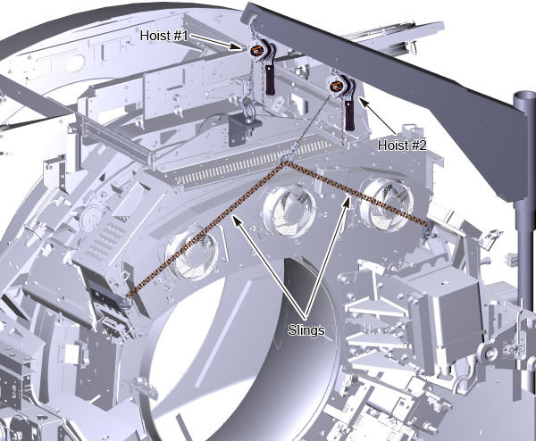
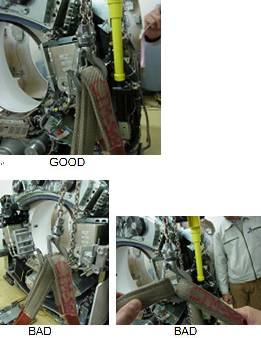
- Attach the sling belts to both sides of the carabineers and
attach the other end of the slings to the hoists #2 (short chain hoist).note:
At this moment, slack can not be removed from slings.
note:Slings should be attached to the hoist hook as Figure 22.
Figure 22. Slings and Hoist Hook
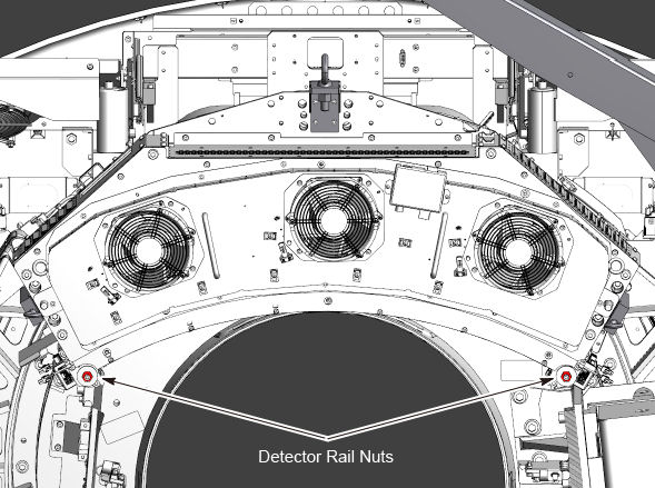
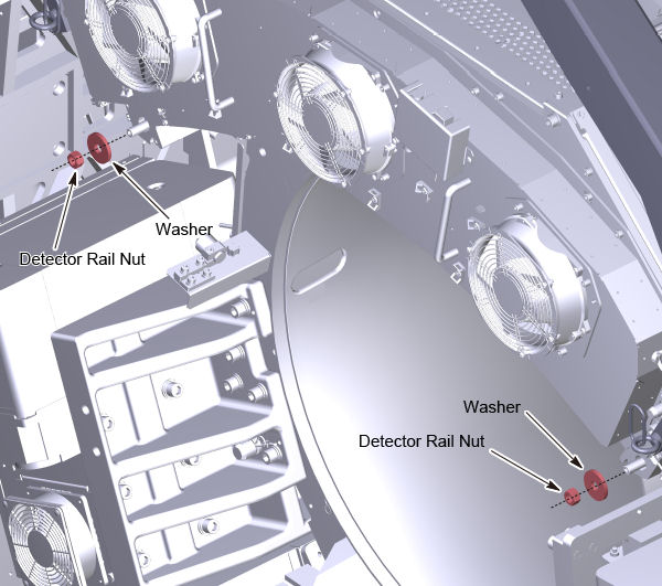
- Loosen 2 detector rail nuts by using M18 socket wrench. (Do
not remove them yet.)note:
If the stud is loosen, use a 18mm box end wrench to remove the rail nuts. The torque for the stud is 66.4 Nm (50 lb-ft).
Figure 23. Detector Rail Nuts
- warning
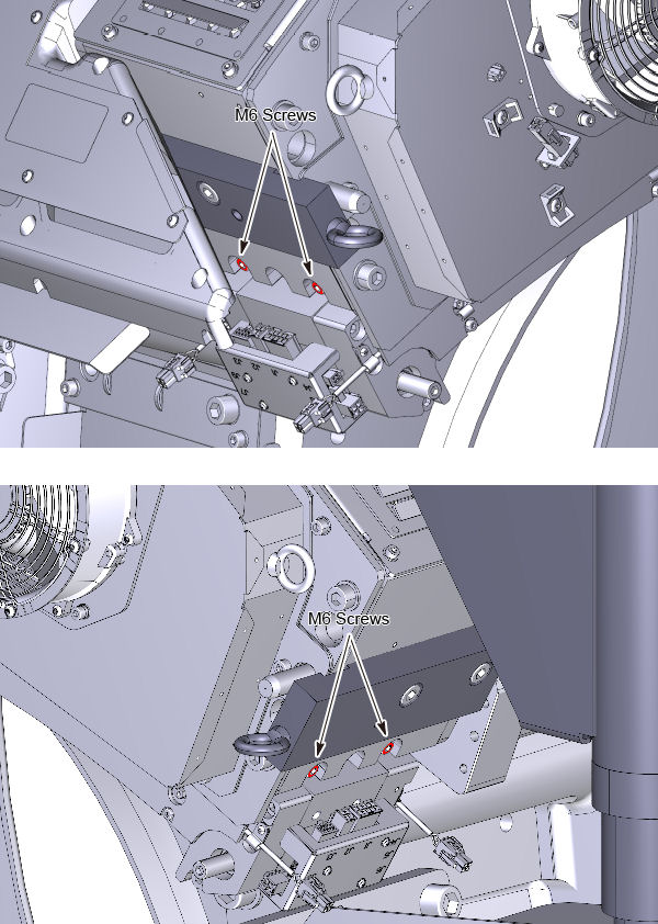
- Fix detector rail to card cage by M6 screws (two for each side).
(Torque: see Table 9)
Figure 24. Fixing M6 Screws

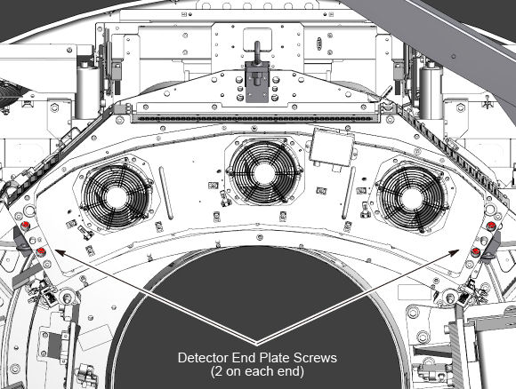
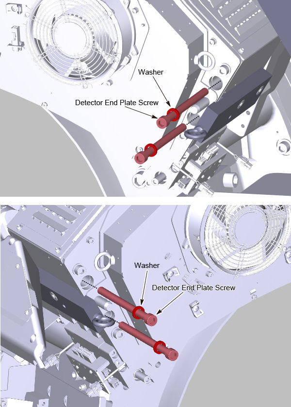
- Remove the 4 detector end plate screws (2 on each end) and discard
the screws and the washers.
Figure 25. Detector End Plate Screws
- Remove 2 detector rail nuts and discard. New nuts are in the supplied mounting kit.
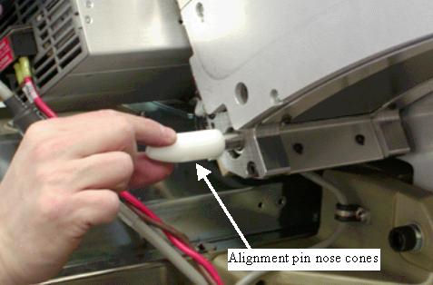
- Attach the alignment pin nose cones on each side of the detector
to protect the threaded ends of the alignment pins during removal
and installation. See Figure 26.
Figure 26. Alignment Pin Nose Cones
- Slowly slide the DAS-Detector assembly away from gantry watching for any cable or other component obstructions.
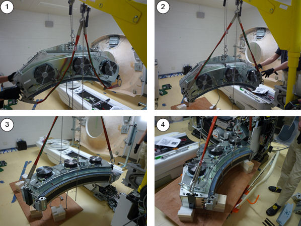
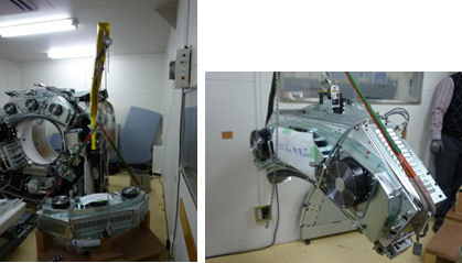
- Lower the DAS-Detector assembly on the back side of the top
cover of the FRU crate temporarily. (Move the defective DAS-Detector
assembly to the FRU crate later.)
Figure 27. DAS-Detector Dismounting
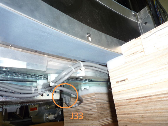
- Remove J33 connector from DAS backplane to avoid damage to the
connector.
Figure 28. J33 Connector
- Remove the hoists, lifting hook and other brackets from the DAS-Detector assembly.
 |
|
7 DAS-Detector Assembly Installation
Procedure
- Attach lifting hook and other brackets to new DAS-Detector assembly.
-
M12 Screw (Torque: 66.4 Nm / 50 lb-ft)
-
M8 Screw (Torque: 19.2 Nm / 14.2 lb-ft)
Figure 29. Lifting Hook Attachment
-
- Attach the hoist #1 to the lift hook and take up slack on the
chain.
Figure 30. Hoist #1 Attachment
- Attach the sling belts to both sides of the carabineers and
attach the other end of the slings to the hoists #2.note:
Slings should be attached to the hoist hook as illustration Figure 31.
Figure 31. Slings and Hoist Hook
- Lift the new DAS-Detector assembly out of the crate. Then, rotate
it to vertical position by adjusting hoists.
Figure 32. New DAS-Detector Lifting
- Move the DAS-Detector assembly toward the gantry and carefully slide the DAS-Detector assembly onto the alignment pins.
- Remove the nose cone alignment pin guides.note:
Use the new mounting hardware (screws, washers and nuts) supplied with the detector.
- Install the new detector end plate screws (2 per side) making
sure the large washers are on the screws. They must have the large
washer required for proper seating. Apply loctite 243 to the screws.
Figure 33. Detector End Plate Screws and Washers
- Torque the 4 detector end plate screws first to the initial
setting and then all 4 to the final settings shown in Table 10 and Table 11.
- Remove the M6 screws (2 per side) that are fixing detector rail
to card cage.
Figure 34. M6 Screws Removal
- Install the detector rail nuts with washers. Apply loctite 243
to the nuts.
Figure 35. Detector Rail Nuts
- Torque detector rail nuts in a 2-step process using the torque
settings shown in Table 12 and Table 13.
- Remove the hoists, lifting hook and other brackets from the DAS-Detector assembly.
- Install the weight support bar and the four rod as follows:
- Apply loctite 263 to two M12 screws, and install the weight
support bar with the two M12 screws. Torque the M12 screws in a 2-step
process using the torque settings shown in Table 14 and Table 15.
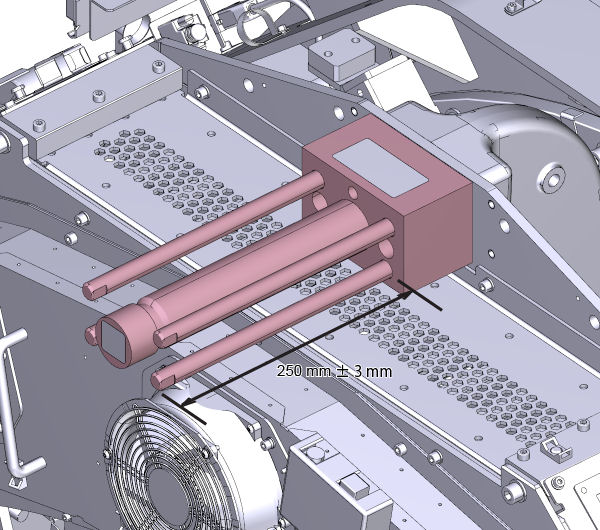
- Apply loctite 263 to four rods, and install them (hand tight)
so that the length of the rod is 250 mm ± 3 mm.
Figure 36. The Length of the Rod
- Apply loctite 263 to two M12 screws, and install the weight
support bar with the two M12 screws. Torque the M12 screws in a 2-step
process using the torque settings shown in Table 14 and Table 15.
- Install the gantry balance weights in the same order as removed. Torque as defined in Gantry Balance Procedure.
- Install the top cover support (Torque 7.9 Nm / 5.8 lb-ft).
- Reconnect DAS cables.
-
Optical cables to CDCB
-
Cables connecting to DAS backplane
-
Fixing the laser harness by tie-wrap
-
- Install DAS Power supply. Torque as defined in Rotating 48VDC PS and Fuse Board Replacement.
- Install SCORP assembly. Torque as defined in ORP Replacement.
- Release the gantry rotational lock.
- Rotate the gantry by hand looking for any potential loose cabling or connectors.
- Install all gantry covers except gantry right side cover. Refer to Replacement → Gantry → Enclosure → (Cover Removal Procedures).
- Turn on the gantry 120VAC at the service switch panel.
- Enable HVDC and gantry axial drive from the service switch panel.
- Install the gantry right side cover.
8 Testing
Flash download may be required. Click the update button, if it is asked.
Procedure
- Perform a gantry balance check and rebalance if needed.
- From the FRDM Process Tool currently open at the console select [Minicheck] and acknowledge
the pop up window if the gantry is ready to rotate.
-
The alignment check will start after the scan button is pressed when prompted. After a while, a set of 2 plots will be shown.
note:Z alignment cal. vector is created using Sweep scan data after closure of plot graph in case of 15HW13.x or later software. That requires removal any obstruction in the path of the beam and Warmup scan, including Mylar window removal. Warm up scan is automatically executed at first.
-
Check the bottom plot to make sure all results are within z alignment specification. See Detector Module Replacement - Merc40 for more instructions if needed.
-
- After exiting the alignment plot, the DAS Tools interface will appear.
- From the DAS Tools interface run the following rotating tests.
- Select and Run [mA Ratio Test] (creates/updates the bad channel map).
- Select and Run the [Auto Test] from DASTools.
- If all the checks pass continue with the next section. If anything fails, troubleshoot per the appropriately failed test.
- Perform any desired quick checks if problem was not a digital issue that was already verified by the mini check tests.
- Perform a tube alignment check per the “Z align” instructions. Adjust the tube if necessary.
- Perform a tube iso alignment check per the “Iso Alignment Procedure”. Adjust the tube if necessary.
9 System Calibration
Procedure
- The detector requires up to 45 minutes to reach operating temperature prior to starting the calibration process. The time to warm up starts from the time the gantry power was turned on. The user message log will indicate when the detector temperature has returned to normal.
- Install Mylar window, if it is removed.
- From the FRDM Process Tool currently open at the console select [Prep for Calibrations]. The Scanner Utilities window will open.
- Perform Collimator calibration using [Scanner Utilities] - [Collimator Cal].
- Perform Full Detailed calibration using [Scanner Utilities]
- [Detailed Cal].note:
CT# adjust is run as part of Detailed Cal, no need to run it separately.
- Perform FastCal using [Daily Prep] - [Fastcal]. (Required after every detailed calibration)
10 Finalization
Procedure
- Perform the Quality Assurance Test.
- From the FRDM Process Tool currently open at the console select [Update Detector Configuration] when the system is ready for customer operation. This will read and update the new detector configuration and perform any background cleanup of temporary software files created by the tool during the replacement process.
- Perform a [Save State] to save the new calibrations.
- Tools Return Policy: Re-package all provided service tools, in the original packages, and place into the FRU shipping container. Failure to return these items will result in your Service Contract being billed the significant cost of these tools.