- Topic ID: id_17423207
- Version: 6.0
- Date: Feb 22, 2022 12:48:36 AM
Detector Module Replacement - Merc40
Prerequisites
Overview
This procedure defines the necessary steps to Remove and Install the Detector Module.
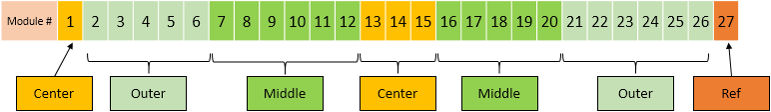
There are three kind of modules used in Merc40 Detector. The following shows the allocation map of module. Center module can be used to slot 27.
Figure 1. Module allocation
1 Preparation
There are two type of Detector module. One is Non-RoHS (old) and another one is RoHS compliant (new).
If Merc40 Detector module part number (part number is applied to the top side of module) is one of the following list, it's Non-RoHS Detector module.
-
5481498 or 5481498-4 MERC40 DETECTOR MODULE KIT CENTER
-
5481498-3 or 5481498-5 MERC40 DETECTOR MODULE KIT OUTER
-
5481499 or 5481499-2 MERC40 DETECTOR MODULE KIT REF27
If it's replaced with RoHS Merc40 detector module, two AGS (Air Guide Seal) shall be replaced ones provided with detector module. Go to AGS replacement procedure AGS replacement procedure for RoHS Detector module.
Procedure
- Move table to home position, fully out and down.
- Remove right side gantry cover.
Refer to Parts Replacement → Gantry → Enclosure → (Cover Removal Procedure).
- Stop the rotor of X-ray tube in case of Liquid Bearing Tube before HVDC off. Refer to Liquid Bearing Tube Rotor stop procedure for details.
- Turn OFF the Axial Drive and HVDC switches on the gantry’s Service Switch Panel.
- Position the detector at 12 o'clock and lock gantry rotation.
- Turn OFF the 120 VAC switch on the gantry’s Service Switch Panel.
- Remove the gantry left side cover, top covers, scan window and front cover.
- Slide out the gantry rear cover and the bore cover.
2 Removal Procedure
Procedure
- Cover the Tube Collimator port to protect it against dropped tools or screws. (Cloth or any other available item)
- Remove the Air Plenum as shown in Detector Air Plenum Removal/Installation.
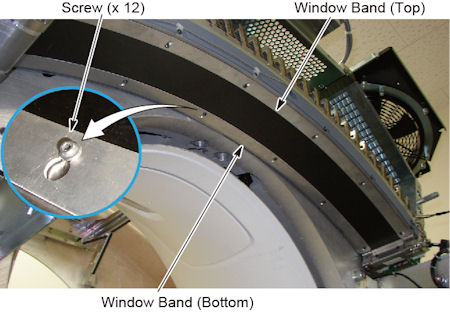
- Loosen 12 screws holding the detector window bands (top and
bottom) to the detector.
Figure 2. 12 screws of Detector Window Bands
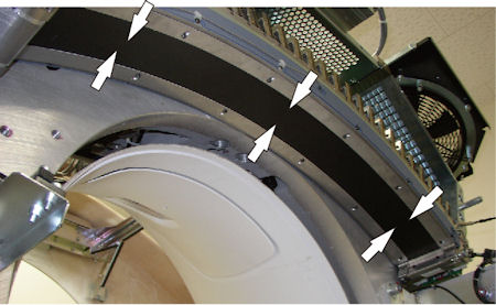
- Slide the detector window bands toward the middle of detector,
and remove them.
Figure 3. Detector Window Bands Removal
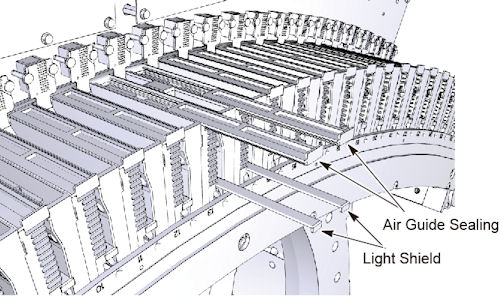
- Remove Light Shield (x 2) and Air Guide Sealing (x 2) from both
sides of the module.
Figure 4. Light Shield and Air Guide Sealing
In case of #1 or #27, remove Light Shield (x1), Air Guide Sealing (x1) and Air Guide Sealing Low (#1) or High (#27), use long hex screw driver to access the screws.
Figure 5. Example of Air Guide Seal High (for Module#27)
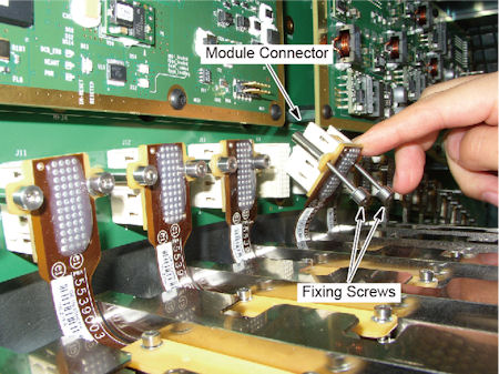
- Loosen 2 fixing screws of the module connector, and disconnect
it.
Figure 6. Fixing Screws and Module Connector
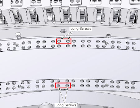
- Remove 4 long screws holding the module to the collimator rails.
Confirm the module number and its location not to remove wrong screws.
Figure 7. 4 Long Screws
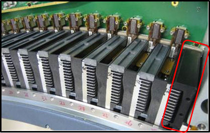
- Carefully pull up the module from the collimator rails.
Figure 8. Detector Module Removal
3 Installation Procedure
Procedure
- notice
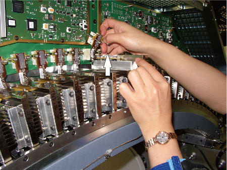
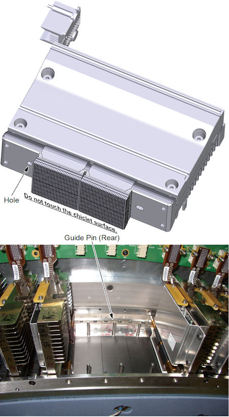
- Install the new module along the rear guide pin of the collimator
unit.
Figure 9. Detector Module Installation
- Tighten the 2 long screws at bottom side (gantry side) first,
and then the 2 long screws at top side (table side) to fix the module
to the collimator rails.
- Connect the module connector, and tighten the 2 fixing screws.
Be careful not to apply damage to the pins.
- Install the two Light Shields and two Air Guide Sealings.
In case of #1 or #27, remove Light Shield (x1), Air Guide Sealing (x1) and Air Guide Sealing Low (#1) or High (#27), use long hex screw drive to fix the screws.
- Install the detector window bands, and tighten the 12 screws
to fix the detector window bands.
- Install the air plenum as shown in Detector Air Plenum Removal/Installation.
- Remove the cloth or any other item from the tube collimator port.
 |
4 Gantry Reassembly
Procedure
- Make sure the Axial Drive, HVDC and 120 VAC switches on the gantry’s Service Switch Panel are OFF.
- Release the gantry rotational lock and install gantry covers,
all except the right side cover.
Refer to Replacement → Gantry → Enclosure → (Cover Removal Procedures).
- Turn on the 120 VAC , HVDC and Axial drive service switches.note:
Flash Download may be required. Click the Update button if it’s asked.
- Rotate the gantry by hands, and confirm no parts hits inside the gantry.
- Install gantry right side cover.
- FRDM Wizard
- Confirm the Tube temperature and the value is less than 400 deg. C. Refer to Tube Temperature Verification .
- Start FRDM Wizard for replacement tab of CSD.
- Confirm that the “Replace Module” is selected, and
press “Start Process” button.
Figure 10. Window - FRDM Wizard
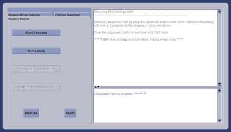 note:
note:Gantry will rotate with 1.0 sec./rev. at next step (MiniCheck).
- Press MiniCheck and follow to the procedure
displayed on the screen.note:
Z alignment cal. vector is created using Sweep scan data after closure of plot graph in case of 15HW13.x or later software. That requires removal any obstruction in the path of the beam and Warmup scan, including Mylar window removal. Warm up scan is automatically executed at first. Also tube temperature shall be specified value on next step.
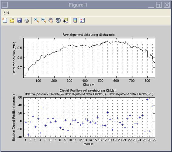
- At first, sweep scan is executed and Z Alignment plot window
is displayed. Confirm that the relative chiclet positions are within
specification. Refer to zalignmentWizard User Instructions (Merc40) how
to manipulate the plot window.
Then execute mA Ratio test and Auto Test in DAS Tools.
Figure 11. Alignment plot window
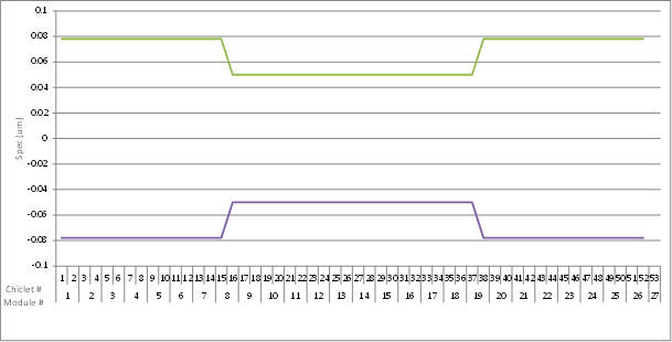
There are two specifications because relaxed specification is applicable for center and mid. area at 15HW13.x or later software (Z alignment cal. is used). See the following table.
Figure 12. Specification of z-position for each Chiclet (graph) (14HW38.14 SP2.2 or earlier)
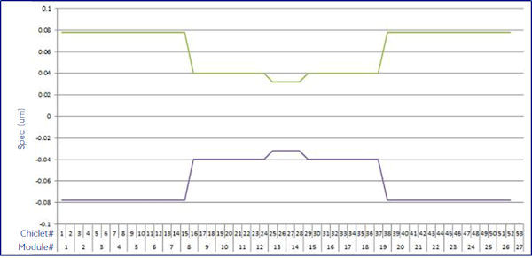
Figure 13. Specification of z-position for each Chiclet (graph) (15HW13.x or later)
- DAS Tool GUI is displayed, then execute mA Ratio test and Auto Test in DAS Tools.
- Press Prepare for Calibration to execute ”Collimator Cal” and “Detailed Cal”
- Perform FastCal using [Daily Prep] - [FastCal]. (Required after every detailed calibration)
- Press Update Detector Config File button to update HART information.
note: New FRU Middle Modules (7-12, 16-20) or Outer Modules (2-6, 21-26), may ship with a few bad pixels on ch2-ch31, The Bad Pixels are only 1x-short LPP, those Pixels will be mapped out during fast cal. The interconnectivity test during fastcal and /or DAS tool test will show the Exclusion zone Passed.If interconnectivity test shows the exclusion Failed, the module should be replaced again.
5 Finalization
Procedure
- Perform the Quality Assurance Test.
- Perform a [Save State] to save the new calibration data.
- Fill out the “Field Return Data Form” included with the module.
- Return the defect part with the form.