- Topic ID: id_17423025
- Version: 4.0
- Date: Jan 20, 2020 8:36:36 PM
Cam Drive Motor and Flex Coupling Replacement
Prerequisites
Overview
This procedures allows you to replace the cam drive motor and flex coupling.
Procedure
- Remove gantry covers as required. See sections on Gantry Cover Removal under Replacement > Gantry> Enclosure.
- Stop the rotor of X-ray tube in case of Liquid Bearing Tube before HVDC off. Refer to Liquid Bearing Tube Rotor stop procedure for details.
- Turn OFF all three (3) gantry service switches Axial Drive, HVDC, 120 VAC).
- Position the gantry with the X-ray tube at 6 o'clock.
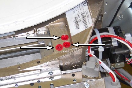
- emove the three (3) red plugs from the Collimator front surface
(on side from which motor will be removed).
Figure 1. Plug Location
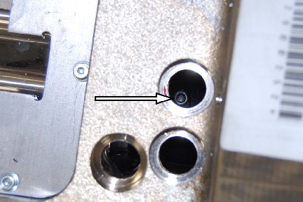
- Rotate the motor, while using a flashlight aimed through the
plug holes to locate the hex-head screw so it can be loosened.
Figure 2. Hex-Head Screw Location
- Using a 3/32 Hex key, loosen the flexible coupling hex-head
screw on the cam side.note:
The Jedi Auxiliary Box will need to be removed to access one of the motors. Rotate the gantry to position the Aux Box in a safe and comfortable position. Engage Gantry Rotational Lock and set Aux Box aside. See Auxiliary Box Replacement procedure for details.
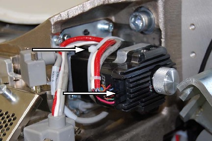
- Disconnect the motor drive connector at the motor and cut the
tie wrap.
Figure 3. Cam Drive Motor Connector and Wire Wrap
- Remove the four (4) hex socket M4 screws holding the motor to the Motor Mount Plate.
- Lift the cam drive motor and flex coupling slightly and disconnect the grommet from the bottom of the assembly, then remove the assembly.
- Using a 3/32 hex key, loosen the hex-head screw and remove the
flex coupling.note:
At this point replace the failed coupling or motor and proceed.
- Install the flex coupling. Place a small drop of Loctite 242 on bottom 3 hex screw threads. Be careful not to over apply. A small quantity on the bottom 3 screw threads will suffice. Torque to 1.2 N-m 11.5 lb-in).
- Install the new motor and tighten the four hex socket screws
to 3.0 N-m (26 lb-in).note:
The replacement motor assembly may have a small circuit board attached. This circuit board is for shipping purposes only and not part of the replacement part. Remove and discard the circuit board prior to installing the new part in the system.
note:Install the Auxiliary Box and Torque all fasteners per Auxiliary Box Replacement procedure. Release Gantry Rotational Lock and proceed.
- Tighten the flexible motor coupling screw. Torque to 1.2 N-m (11.5 lb-in).
- Connect the motor drive connector at the motor and replace the tie wrap.
- Install the three (3) plugs.
Finalization
- Perform the following procedures in this order: