- Topic ID: id_17423050
- Version: 3.0
- Date: Apr 22, 2019 12:56:28 AM
Auxiliary Assembly Replacement
Prerequisites
Overview
This procedure describes how to:
-
Replace Auxiliary Assembly
-
Run application scan(s) to verify system operation
1 Auxiliary Assembly Removal
Procedure
 danger
- Move table to its lowest elevation.
- Remove power to the gantry using proper Lockout/Tagout procedures.
- Remove side top and front gantry covers.
- Stop the rotor of X-ray tube in case of Liquid Bearing Tube before HVDC off. Refer to Liquid Bearing Tube Rotor stop procedure for details.
- Turn OFF all 3 switches (Axial Drive, HVDC, 120VAC) on the Service Switch Panel.
- Remove power at main disconnect (A1) panel. Use proper Lockout/Tagout procedures.
- Rotate the Gantry until the Auxiliary Assy reaches the 3 o’clock position.
- Engage gantry rotational lock.
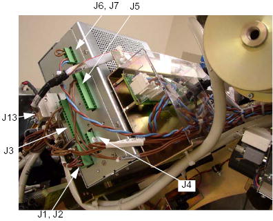
- Cut any tie-wraps holding the cables to the Auxiliary Box
- Disconnect the following cable connector from the Auxiliary
Box.
-
J1/J2 Connector (<-> HEMIT Tank/Power Unit)
-
J3 Connector (<-> HEMIT Tank)
-
J4 Connector (<-> Power Unit)
-
J5 Connector (<-> Power Unit)
-
J6/J7 Connector (<-> TB1)
-
J13 Connector (<-> Power Unit)
Figure 1. Auxiliary Box Cable Connections
-
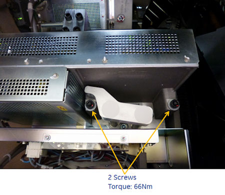
- Unscrew the 2 screws, and remove the auxiliary box from the
Gantry.
Figure 2. Auxiliary Box Removal
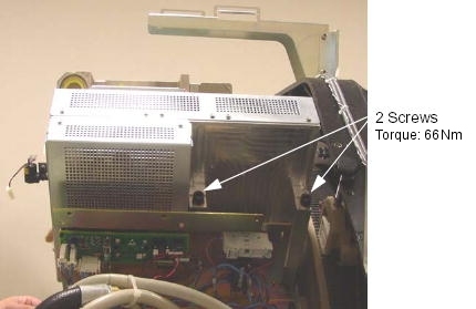
Figure 3. Auxiliary Box Removal - Cj M40
2 Auxiliary Box Installation
Procedure
- Ensure that Lockout/Tagout procedure has been applied, and that gantry power is removed.
- Ensure that gantry rotational lock is engaged and gantry does not rotate by attempting to rotate gantry by hand.
- Place the new auxiliary box.
- Torque the two screws to the following pre-load value.
- Torque the two screws to the following final value.
- Torque the two screws to the following pre-load value.
- Connect the all cable connectors of the Fan Inverter.
- Fasten the cables to the auxiliary box using tie-wraps.
3 Finalization
Procedure
- Perform Gantry Rotation Safety Check.
- Perform Gantry Balance Procedure.
- Perform Meter verification.note:
(For GE Healthcare Personnel Only) For supported software releases, perform High Voltage Tank Feedback Resistor Verification (Restricted) and Internal Scan Timer Verification (Restricted) procedures instead of High Voltage Tank Feedback Resistor Verification procedure.
- Perform HV Tank Feedback Resistor Verification.
- Perform Filament calibration (Generator Tool).
- Perform HHS Scans.
- Perform System Scanning Test .
- Perform Quality Assurance Test.