- Topic ID: task_ijb_5q2_znb
- Version: 3.0
- Date: Feb 3, 2021 2:11:38 AM
(19BW35.27) Load From Cold
Prerequisites
Overview
The following procedure describes and illustrates the system software loading process commonly referred to as the Load From Cold (LFC). It is important to follow the steps listed below in order.
1 Software Deliverable
Procedure
- CT Operating System and Applications Software.
2 Pre-LFC Checks and Information Gathering
Procedure
- Confirm that a current System State Backup Media is on site. If unsure of the status of the System State, execute section Save System State (Approximately 10 minutes) to save a System State Backup to USB Flash Drive.

- notice
- Remove USB Flash Drive from the host computer before starting the OS Load of the LFC process.
3 Information Capture
3.1 Common Information Capture
Procedure
- Record Autovoice Volume control settings (ALT-F3 by Toolchest, upper right corner).
- Write down all of the system INFO information on the reconfig screens, including the network information.
- notice
- Verify and record specific system hardware configuration.
- Open a shell and type the following:
{ctuser@hostname}cat /usr/g/config/INFO
- Record screen information.
- Open a shell and type the following:
- If the console has Connect Pro installed, write down the information when you run installhisris so it can be entered on the new console when installing the Connect Pro option.
- Close the Service Desktop window in the upper left corner of the screen.
3.2 Information Capture for Option Installation
If your system does NOT have Exam Split option, skip this section. Perform these steps before powering down your current Operator Console:
- Open a Unix Shell and type the following:
- {ctuser@hostname} su -
- Password: <password>
- [root@hostname] ls -l ~ctuser/ves/.hesMode
note: There are no spaces in the phrase ~ctuser/ves/.hesMode - Examine the results.
- If the results are similar to:
-rw-r--r-- l ctuser users 0 Apr 3 12:43
/usr/g/ctuser/ves/.hesMode
The HES (Hard Exam Split) mode is configured.
- If the results show 'No such file or directory', then VES (Virtual Exam Split) mode is configured.
- If the results are similar to:
- Record Exam Split Mode (Hard or Virtual). This info will be used during the LFC Options Installation.
- Close the Unix Shell.
4 Save System State (Approximately 10 minutes)
Procedure
- Plug the USB Flash Drive into the Host Computer.
- Open Service Desktop and select Utilities.
Figure 1. Common Service Desktop (CSD), Utilities Tab
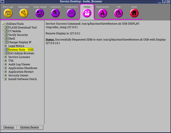
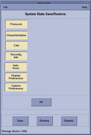
- Select System State - USB and select All, then pressSave in the opening window.
Figure 2. Save System State Window
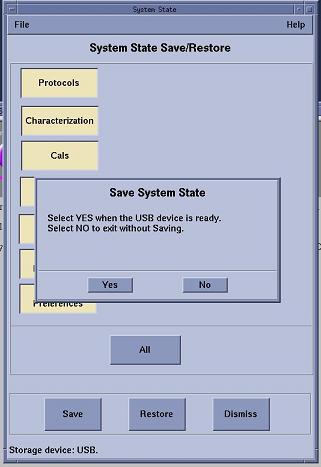
- Click Yes in the System State Media Ready pop-up window to start the save process.
Figure 3. System State USB Media Ready Pop-up Window
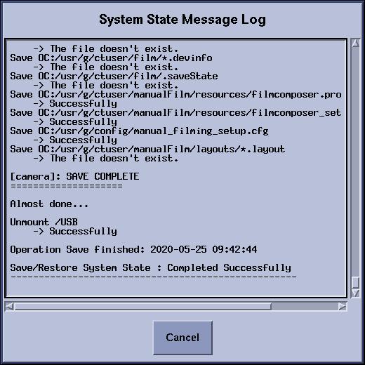
- Verify that the Save of System State was successful. A message at the end of the System State Message Log Window should state: Save/Restore System State: Completed Successfully.
Figure 4. System State Message Log Window
- When completed, click Cancel in the System State Message Log Window, then Dismiss in the System State Media Ready Pop-up Window.
- Close the Common Service Desktop window.
5 Check BIOS/RAID States
- BIOS version is 2.47
- RAID1 is configured
Procedure
- As soon as HPZ8G4 Host power-on, confirm BIOS version is 2.47 displayed at lower-left corner of monitor screen, skip directly to OS/APPs load procedure.
Figure 5. Monitor Screen
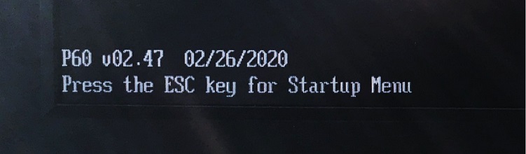
Otherwise, reference HP Z8G4 BIOS Flashing and Recovery to upgrade BIOS, then confirm correct BIOS settings match Table 5.
- If BIOS upgrade procedure is done in step 1, RAID1 setting must be performed by referring to RAID Setup Procedure .
6 Operating Software (OS) Load (Approximately 20 minutes)
Procedure
- Confirm that the USB Flash Drive been plugged into the Host Computer. If not, plug the USB Flash Drive into the Host Computer again.
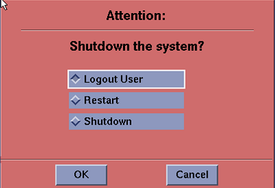
- Press Shutdown and select Restart.
Figure 6. System Shutdown Attention Window
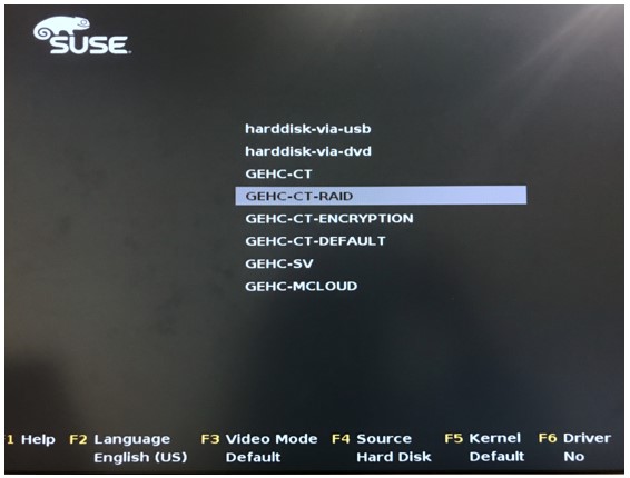
- As the Host Computer restarts, the boot process GUI appears. Select GEHC - CT -RAID.
Figure 7. OS Boot Screen Prompt
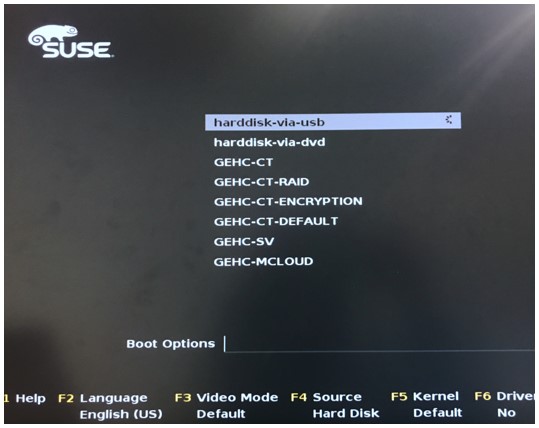
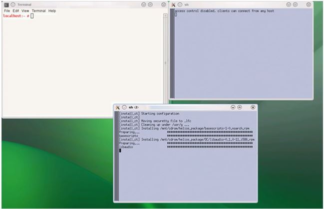
- During the OS installation, host reboot happens (See Figure 8). The first line is selected by default, do NOT take any action. Wait for a moment until OS installation completion.
Figure 8. During the OS Installation
 note: Dual Monitor Displays: From this point in the procedure, only right side monitor display will appear. This is normal, do not move monitor video cables! This condition will be resolved after the Application Software is loaded on the system.
7 Applications Software (APPS) Load (Approximately 80 minutes)
Procedure
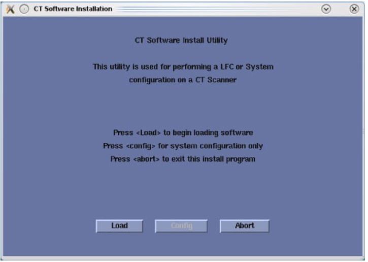
- Select Load in the CT software installation window.
Figure 9. Apps Load Command Window
- System State decision for Install INFO decision box will appear.
Select Yes, then continue with Step 3.
Figure 10. Install INFO Window
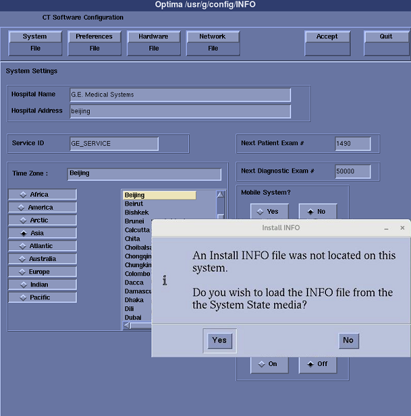 note: If a valid and current System State Backup media is not available, answer [No] and manually configure the Hardware Tab to define System and Console Type in accordance with the procedure Manually Configuring System INFO. Then all Tabs including System, Preferences, Hardware, Network and Security can be reviewed and modified.note: If System State is NOT used, mini check of FRDM Wizard shall be executed in order to create Z Alignment Cal. vector. That is needed for scanning.
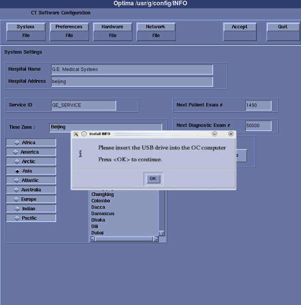
 - System State (Install INFO) window will appear.
Press OK.
Figure 11. System State Window
- The Install INFO on the System State Backup Media will be read and an INFO window will become active.
Select Accept.
Figure 12. Install INFO - Accept Window

- The Install INFO on the System State Backup Media will be displayed and a confirmation window will appear.
Select YES.
Figure 13. Install INFO - Confirm Window
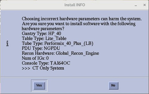 note: Install INFO detail in illustration will differ depending on System type. Verify that the Install INFO detail is correct for the system before selecting YES.
 - System Install INFO will be now used to create the CT Applications load routine. Do not remove the USB Flash Drive until completed.
Figure 14. CT Applications Software Load Windows
- When completed, the Operator Console will automatically reboot.
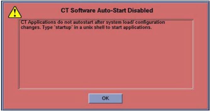
- After the Host Computer reboots, a pop-up window will appear.
Click OK to close window.
Figure 15. CT Software Auto-Start Disabled Pop-Up Windows
 note: Remove all USB media from Host USB ports.
 - Right click on black screen, then click unixshellleft or unixshellright, type st [ENTER], start the system.
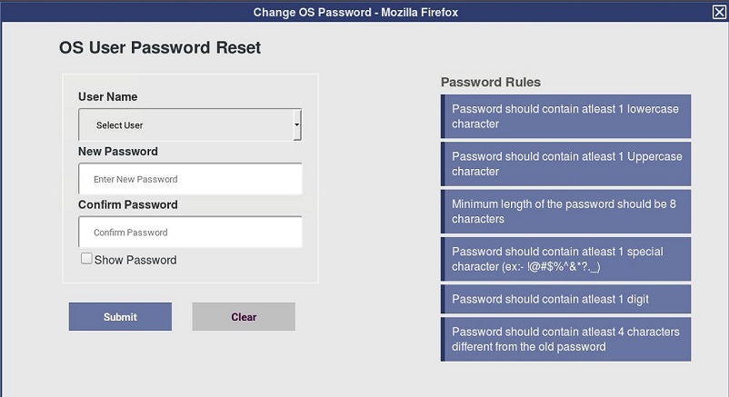
- When CT APPS starts up, it will be waiting at below window until you close it. Details, refer to OS User Password.
Figure 16. OS User Password Reset Window
8 Restore System State (Approximately 10 minutes)
Procedure
- Insert a previously saved USB Flash Drive into the Host Computer.
- Select System State - USB (see Figure 1) and select All then press Restore (see Figure 17) in the opening window.
Figure 17. Restore System State Window
- Click Yes in the Restore System State window to start the restore process.
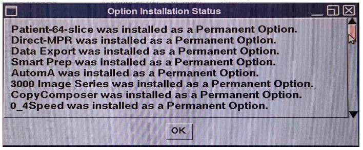
- A shell window will open and the System Stated will be restored. A pop-up window will appear reminding that options have been installed.
Click OK to close window.
Figure 18. Option Installation Status
9 Service Pack Installation
Procedure
- If exists, install Service Pack. Refer to Service Pack Installation Procedure for this software version.
10 Flash Download (Approximately 20 minutes)
Procedure
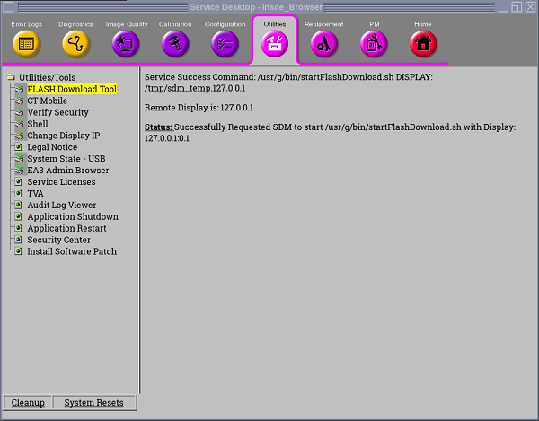
- Perform the Flash Download Utility found on the Common Service Desktop–Utilities Tab, select Flash Download.
Figure 19. Common Service Desktop - Utilities Tab, Flash Download
- When the Flash Download Window opens.
Select Query.
Figure 20. Flash Download Window
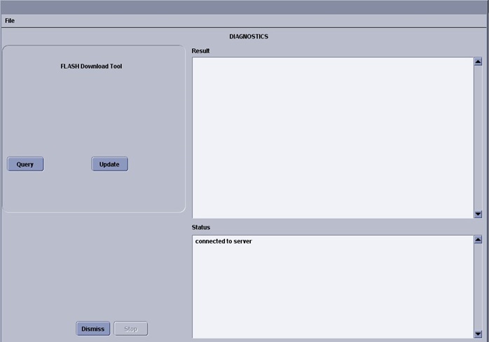
- Once the Gantry Hardware Flash Downloads successfully, select Dismiss. If some failure occurs, select Update and repeat until all Status is OK.
- Close the Common Service Desktop.
- Reconnect the Hospital Network cable at the rear of the Operator Console that was disconnected at the beginning of the LFC.
- Select Shutdown icon on the Desktop and restart the system.
11 NanoCloud AWS Installation
12 Final Save System State
Procedure
- Perform the System State Save Restore procedure and save a System State Backup to USB Flash Drive.
- Backup to USB Flash Drive. Save the System State Backup media in a safe and secure location for future service activity.
13 Finalization
Procedure
- Perform System Scanning Tests in the Functional Checks chapter of this manual to confirm proper operation.
- Reinstall Console Front Cover.