- Topic ID: id_11038728
- Version: 4.0
- Date: May 23, 2022 11:26:21 PM
HV Tank Replacement
Prerequisites
Procedure summary:
-
Remove power unit mounting screws
-
Change HV Tank
-
Remount power unit
-
Reattach wring
1 HV Tank Removal
Procedure
 danger
- Remove the power unit according to Power Unit Replacement.
- With the 10 mm Allen wrench, only loosen the three bolts (located at the bottom of the inverter casting) which fasten the HV Tank to the heat sink. Then, only remove the central bolt.
- Remove covers.
- Unscrew the 5.5 mm hex head screws from three sides and remove the front cover.
- Unscrew and remove the lifting bracket plate A.
Figure 1. Lifting Bracket Plate
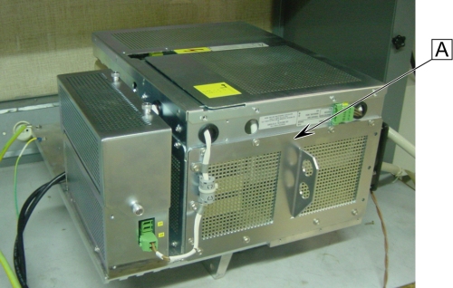 note: All the 5.5 mm hex head screws on the Jedi generator are 8 mm long, except for the fourteen screws holding the lifting bracket, which are 12 mm long.
 - Unscrew and remove the left cover (with fan), but don't remove the fan from its bracket.
- Remove the 2 remaining bottom screws holding the HV Tank through the inverter heat sink.
- Position the Power Unit on its side, the heat sink down.
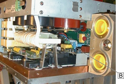
- Disconnect the short ribbon cable from the KV Measure board
to the Gate Command board B.
Figure 2. Short Ribbon Cable
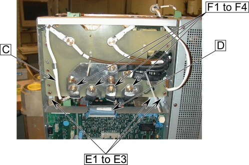
- Disconnect the Heater Cable C from the KV Measure board.
- Disconnect the short ribbon cable D from the KV Measure board to the PPC board.
- Disconnect the three 5.5 mm hex head screws E1 to E3 from plate.
- Disconnect the 4 primary flat cables F1 to F4 frm the capacitor
assembly nuts (socket 13).
Figure 3. Cable Connection of KV Measure Board
- Pull out the HV Tank by sliding it (be careful about primary flat cables position).
2 HV Tank Installation
Procedure
- Push in the new HV Tank by sliding it (be careful about primary flat cables position).
- Reconnect the heater cable C to the KV Measure board.
- Reconnect the short ribbon cable D coming from the PPC board to the KV Measure board.
- Remount the three 5.5 mm hex head screws E1 to E3 to plate, tighten all of them to 2 Nm (20 kg.cm).
- Reconnect the 4 primary flat cables F1 to F4 to the capacitor
assembly nuts (socket 13), torque the four M8 nuts to 10 Nm.
Figure 4. Cable Connection of KV Measure Board
- Reconnect the short ribbon cable coming from the Gate Command
board B to the KV Measure board.
Figure 5. Short Ribbon Cable
- Remount the 2 bottom crews (holding the HV Tank through the heat sink) without tightening (not the central one).
- Position the Power Unit vertically.
- Remout the remaining central bottom screw (holding the HV Tank through the heat sink) without tightening.
- Remount the left cover (with fan).
- Remount the lifting bracket plate A.
Figure 6. Lifting Bracket Plate
note: All the 5.5 mm hex head screws on the Jedi Generator are 8 mm long, except for the fourteen screws holding the lifting bracket, which are 12 mm long, tighten all of them to 2 Nm (20kg.cm). - Remount the 5.5 mm hex head screws from three sides and remount the front cover.
- With the 10 mm Allen wrench, tighten the three bolts (located at the bottom) which fasten the HV Tank to the heat sink, torque the 3 M12 screws to 66.4 Nm.
- Remount the Power Unit according to Power Unit Replacement.
3 Finalization
Procedure
- Perform Gantry Rotation Safety Check.
- Perform Gantry Balance Procedure.
- Perform Meter verification.
- Perform HV Tank Feedback Resistor Verification.
- Perform Filament calibration.
- Perform HHS Scans.
- Perform System Scanning Test.
- Perform Quality Assurance Test.