- Topic ID: id_11038838
- Version: 3.0
- Date: Jun 10, 2020 2:24:16 AM
Gantry Balance Procedure
Prerequisites
Overview
This procedure should be performed whenever the rotating Gantry is serviced. It is intended to 1) , and 2) .
-
Check or create sensitivity matrix.
-
Balance the gantry in both static and dynamic vectors.
Procedure
- notice
- Review the information in the Safety section above.
-
The physical order from front to back is critical and cannot be altered.
-
A quantity of 0 (zero) is a valid number for specific weights.
-
Each specific weight is defined by its base metal, generic name, location angle and thickness in mm.
Example:
-
Base Metal: Aluminum
-
Generic Name: SPACER
-
Location Angle: 180 DEG
-
Thickness in mm: 25.4MM
note: You may not have all plate types installed on your Gantry depending on what is needed to balance the Gantry. -
-
- Position the Table at its lowest position.
- Remove the gantry right side cover.
- Disable Axial Drive, HVDC, and 120 VAC service switches from the service switch panel.
- Remove the Gantry left side, top, and front covers.
Refer to
- On the gantry right side, connect the front and rear cover cables containing the E-Stop circuit to the terminators on the gantry frame. Only one cable from the front and rear will connect, there is no chance to choose wrong.
 danger
- Enable the 120 VAC, HVDC and Axial Drive service switches from the service switch panel in order to run the balance test.
- notice
- Gantry balance adjustment shall be followed below procedure.
All rotating parts shall be installed before this step
-
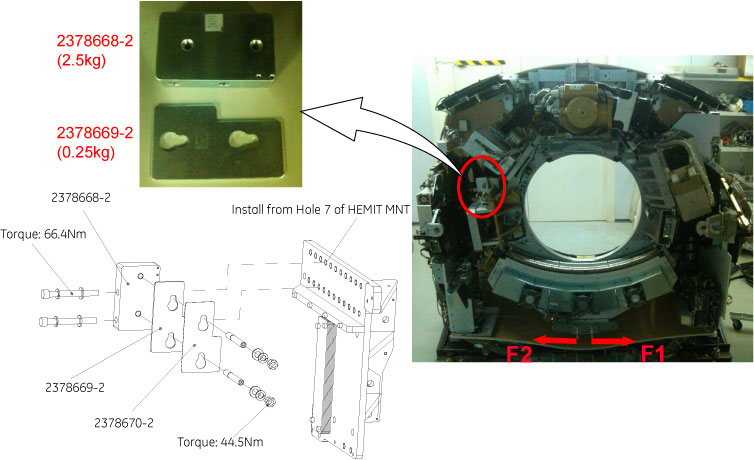
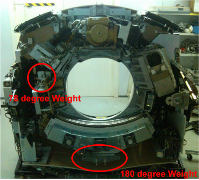
Gantry balance adjustment for 78 degree weights
-
First set Gantry of 78 degree weight at horizontal position, then measure F1 and F2 with spring scale as shown below illustration.
Figure 1. 78 Degree Weights Adjustment
 note:
note:There are only three 78 degree weights (2378669-2, shipped with shipping collector) on site, if need more 78 degree weights to adjust gantry balance, please order 2378668–2 and 2378669–2 according the actual needs.
note:Along tangential direction.
-
If F2 > F1, decrease weight, until |[F2-F1]| / 2 ≤ 0.25 Kg; otherwise increase weight, until |[F2-F1]| / 2 ≤ 0.25 Kg. Refer to Table 4
-
-
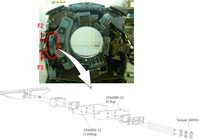
Gantry balance adjustment for 180 degree weights
-
First set Gantry of 180 degree weight at horizontal position, then measure F1 and F2 with spring scale as shown in below illustration.
Figure 2. 180 Degree Weights Adjustment
 note:
note:If the quantity of 180 degree weights (shipped with shipping collector) can not meet gantry balance adjustment, please order 2342895-11 and 2342895-12 according the actual needs.
note:Along tangential direction.
-
If F2 > F1, decrease weight, until |[F2-F1]| / 2 ≤ 0.25 Kg; otherwise increase weight, until |[F2-F1]| / 2 ≤ 0.25 Kg. Refer to Table 5
-
-
- Make sure to torque all fasteners as instructed.
Be sure the nuts on four threaded rods are tight in the 180-degree location. Use the Torque wrench ordered from the tool depot to tighten nuts to 160N-m (118 ft-lbs). This torque wrench is a 1/2" drive to match the deep well socket and is capable of 250 ft-lbs.
In the 78-degree location, tighten the two M12 nuts to 44.5N-m (32.8 ft-lbs), and tighten the two M12 cap screws to 66.4N-m (48.9 ft-lbs).
Be aware that adjacent nuts might loosen when a nut is tightened due to the springiness of the stack. Use a diagonal type pattern (similar to tightening tire lug nuts) to tighten the nuts and go back to verify all are still torqued properly when complete. Refer to Gantry Balance Theory for further discussion regarding the importance of torque on the weights.
 |
 |
|
Finalization
- Disable the Axial Drive, HVDC and 120 VAC service switches from the service switch panel.
- Install the front cover (and rear if removed), top covers and left side cover.
- Enable the 120 VAC, HVDC and Axial Drive service switches from
the service switch panel and install the gantry right side cover.
Remember to enable the table drives using the push button on the bottom right of the service switch panel or using the front cover enable button.
- Perform FASTCAL. Ensure no pop-up windows occur and gesyslog is error free.