- Topic ID: id_11039075
- Version: 3.0
- Date: May 23, 2022 11:26:01 PM
DoD Detector Replacement Procedure
Prerequisites
This procedure defines the replacement process for DoD detector ASM.
1 System Preparation
Procedure
- At the console start the Replacement > FRDM Wizard from the Common Service Desktop Replacement tab. Figure 1 shows the main
screen.
Figure 1. Process Tool
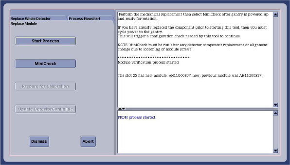
- Select the Replace Whole Detector tab and then Start Process. This will set up the system software to prepare for a detector replacement. The physical replacement can now be performed.
- Move the cradle full back out of the gantry and move it full down to allow you to completely move the front cover away from the gantry.
- Remove the gantry right side cover and disable “Axial Drive” and “HVDC” switches from the service switch panel.
- Position the detector at 12 o'clock and lock gantry rotation.
- Turn OFF “Axial Drive”, “HVDC”, and “120VAC” switches on the service switch panel.
- Remove all gantry covers.
- Cover the Tube Collimator port to protect it against dropped tools or screws. (Cloth or any other available item)
2 FRU container handling
Foam block on ramp is attached by velcro. Pull foam block off to ease aluminum crate removal.
3 Vyper Plenum ASM Removal
Procedure
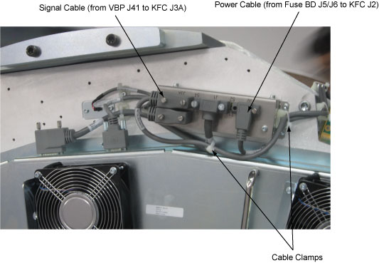
- Release the cable clamps holding the fan controller power cable and signal cable. (See Figure 2)
- Disconnect the cable connectors from the KFC J2 and J3A.
Figure 2. Release the Cable Clamps and Disconnect the Cable Connectors
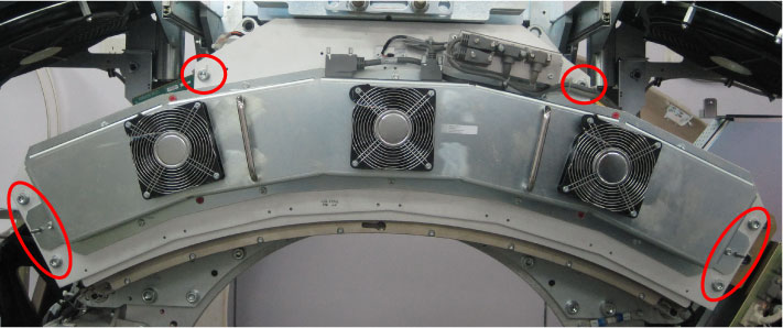
- Remove the Vyper plenum ASM by unscrewing its six M10 head cap
screws.
Figure 3. Vyper Plenum ASM Removal
4 DoD Detector Removal
The order of the following steps is critical to success. Do NOT change the order. Read each step and cautions completely prior to performing that step.
Procedure
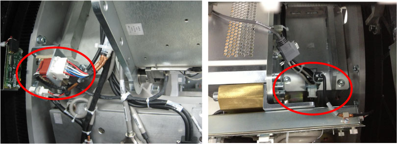
- Release the cable clamps holding the detector cables.
- Disconnect the cable connectors from both sides of the detector.
Figure 4. Disconnect the Detector Cable Connectors
- Make sure ESD strap is in use prior to continuing.
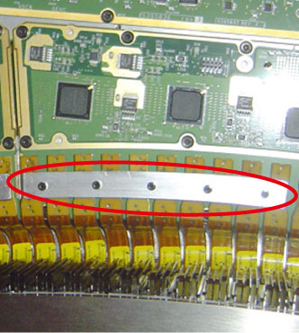
- Remove the plates from the three DIFBs (Interface Board) by
unscrewing its screws.
Figure 5. Plate for Flex Cable
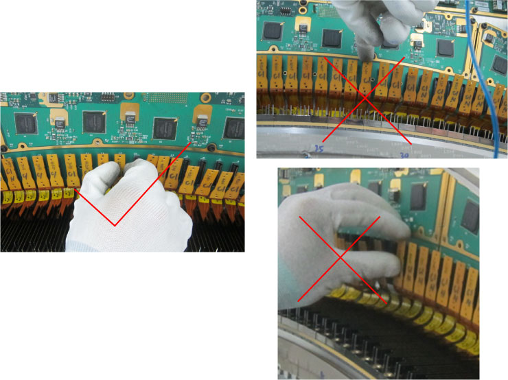
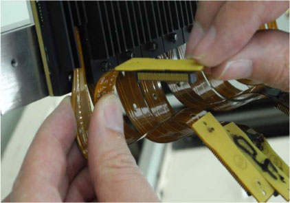
- Disconnect all 49 flex-cable connectors from the three DIFBs
(Interface Board).
Correct way: Hold the edge of connector and unplug smoothly out, no tilt and shake.
Figure 6. Method for Disconnecting the Modules from the DIFBs
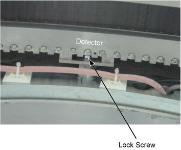
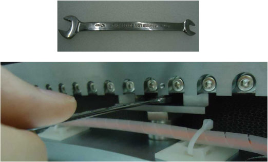
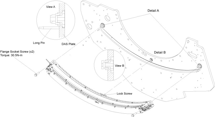
- Unscrew the lock screw with wrench as shown in Figure 7.
- Unscrew the two flange socket screws from both sides of the
detector and remove the detector carefully. (See Figure 7)note:
The bottom face of the detector (DoD module) is very sensitive, so handle it with extreme care.
Figure 7. DoD16 Detector Removal
5 DoD Detector Installation
Procedure
- Unpack all the transportation packaging for the new DoD detector.note:
The new detector comes with a cover plate installed to protect the modules during shipment. Leave this cover in place until the detector is mounted on the gantry.
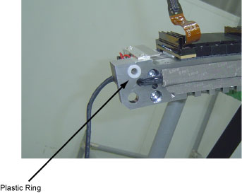
- Verify that the two insulator plastic ring are securely attached
to mounting holes on both sides of the detector.
Figure 8. Insulator Plastic Ring
- Bend the flex cable to the certain shape as shown in Figure 9.note:
Bend softly the flex cable, otherwise the flex cable may cause permanent damage.
Figure 9. Bend Flex Cable
- Hang the detector on the DAS detector plate, let two long pins insert both plastic rings of the detector. (See Figure 7)
- Secure the lock screw with torque 13.5N-m. (See Figure 7)
- Securely two flange socket screws with torque 30.5N-m. (See Figure 7)
- Reconnect all 49 flex-cable connectors to the three DIFBs (Interface
Board).note:
Clean the flex-cable connectors and DIFBs with the aero-duster before connecting flex-cables and make sure the flex-cables are securely connected to the DIFBs.
- Reconnect and fasten cable connectors of the detector.
6 Vyper Plenum ASM Installation
7 Replacement Completion
Procedure
- Turn on the gantry 120VAC switch at the service switch panel.
- Release the gantry rotational lock.
- Rotate the gantry by hand looking for any potential loose cabling or connectors. Review the cable routing to make sure it is consistent with the definitions in this section and not any interference.
- Enable HVDC and Axial Drive switches at the service switch panel.
8 Testing
Procedure
- From the FRDM Process Tool currently open
at the console select Minicheck and acknowledge
the pop up window if the gantry is ready to rotate.
-
The alignment check will start after the scan button is pressed when prompted. (Non-rotating scan). After 2 minutes a set of 2 plots will be shown.
-
Check the bottom plot to make sure all results are less than +/- 75. See zalignmentWizard User Instructions for more instructions if needed.
-
Since the complete detector has just been replaced, the alignment check should pass without issue. If any module is out of alignment, use the FRDM Replacement Procedure to realign the module.
-
- After exiting the alignment plot, the DASTools interface will appear. Run “mA Ratio Test” to update the bad channel map for the new detector.
- From the DASTools interface run the following
rotating tests.
- Select and Run mA Ratio Test (creates/updates the bad channel map)
- Select and Run the Auto Test from DASTools.
- If all the checks pass continue with the next section. If anything fails, troubleshoot per the appropriately failed test.
- Perform any desired quick checks if problem was not a digital issue that was already verified by the mini check tests.
- Perform a tube POR alignment check per the “Plane of Rotation (POR) Alignment Process” instructions. Adjust the tube if necessary.
- Perform a detector BOW alignment check per the “Beam-on-Window (BOW) Alignment Process” instructions. Adjust the detector if necessary.
- Perform a collimator CBF alignment check per the “CBF/SAG Alignment Process” instructions. Adjust the collimator if necessary.
- Perform a tube ISO alignment check per the “ISO Alignment Process”. Adjust the tube if necessary.
- Perform a gantry balance check and rebalance if needed.
9 Gantry Reassembly
Install all gantry covers remembering to enable Axial Drive switch just before installing gantry left side cover. Gantry covers MUST be in place prior to running calibrations. Refer to
10 System Calibration
Procedure
- The detector requires up to 45 minutes to reach operating temperature prior to starting the calibration process. The time to warm up starts from the time the gantry power was turned on. The user message log will indicate when the detector temperature has returned to normal.
- From the FRDM Process Tool currently open at the console select Prep for Calibrations. The Scanner Utilities window will open.
- Perform Collimator calibration using Scanner Utilities - Collimator Cal.
- Perform Full Detailed calibration using Scanner Utilities - Detailed Cal.note:
CT# adjust is run as part of Detailed Cal, no need to run it separately.
- Perform FastCal using Daily Prep – Fastcal. (Required after every detailed calibration)
11 Finalization
Procedure
- Perform the Quality Assurance Test.
- From the FRDM Process Tool that currently open at the console select Update Detector Configuration when the system is ready for customer operation. This will read and update the new detector configuration and perform any background cleanup of temporary software files created by the tool during the replacement process.
- Perform a Save State to save the new calibrations.
-
Tools Return Policy: Re-package all provided
service tools in the original packages, and put into the FRU shipping
container. Failure to return these items will result in your Service
Contract being billed the significant cost of these tools.
-
Detector lift hook
-
Nylon thread protectors (white nose cones)
-