- Topic ID: id_11038744
- Version: 3.0
- Date: May 23, 2022 11:25:56 PM
FRDM Replacement Procedure
Prerequisites
This procedure must be followed in order of the steps given to avoid potential hardware damage to the detector and to have the highest chance.
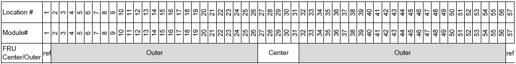
Figure 1. Channel Map
1 Special Tools overview
Procedure
-
Figure 2 shows the special tools shipped with the new module.
Figure 2. Special Tools
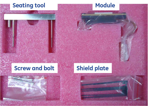
The controlled seating tool is used while installing a module to make sure the alignment pins on the module are centered on the detector collimator to avoid any damage to the detector collimator plates during module insertion.
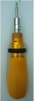
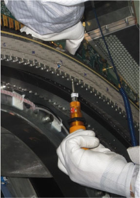
- Torque (1.1 N.m) screw driver, M4 Hex-socket drive bit
- Torque (2.5 N.m) screw driver, M4 Hex-socket drive bit
- Torque (1.0 N.m) screw driver, M3 Hex-socket drive bit
Figure 3. Torque Screw Driver
2 Preparing the System
Procedure
- If replacing a center module (slots 27-31) perform the following steps. Otherwise go to Step 2.
- From a C-shell type enableBISfeature. If this has already been done in the past, the message will indicate that this function is already enabled.
- If the system did not indicate that the feature was already enabled then a console reboot is necessary to put the change into effect.
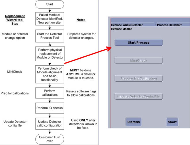
- At the console start the Replacement > FRDM Wizard from the Common Service Desktop Replacement tab. Figure 4 shows the main
screen.
Figure 4. Process Tool
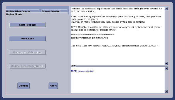
- Select the Replace Module tab and then Start Process. This will set up any necessary preconditions needed in the system software to prepare for a detector module replacement. The physical module replacement can now be performed.
- Move the cradle full back out of the gantry and move it full down to allow you to completely move the front cover away from the gantry.
- Remove the right side gantry cover and disable Axial Drive and HVDC switches from the service switch panel.
- Position the detector at 12 o'clock and lock gantry rotation.
- Shut down all gantry power from the service switch panel.
- Remove the side, top, front and rear gantry covers.
- Turn power on to the table to allow the table to be moved to full up position to use as a work table. Then power down again.
3 Vyper Plenum ASM Removal
Procedure
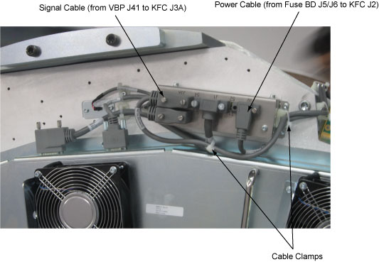
- Release the cable clamps holding the fan controller power cable and signal cable. (See Figure 5)
- Disconnect the cable connectors from the KFC J2 and J3A.
Figure 5. Release the Cable Clamps and Disconnect the Cable Connectors
- Demount the Vyper plenum ASM by unscrewing its six M8 head cap
screws.
Figure 6. Vyper Plenum ASM Removal
- Cover the Tube Collimator port to protect it against dropped
tools or screws. (Cloth or any other available item)
Figure 7. Collimator Protection (Example)
4 FRDM Removal
 |
|
Procedure
- Make sure ESD strap is in use prior to continuing.note:
The order of the following steps is critical to success. Do NOT change the order. Read each step and cautions completely prior to performing that step.
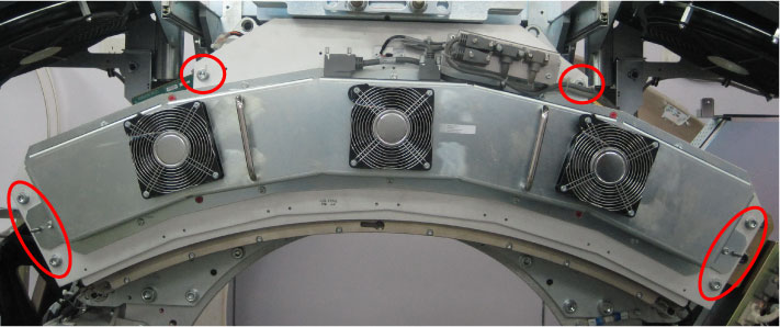
- Remove the two light shield brackets (red circles) from both
sides of the detector by unscrewing its screws.
Figure 8. Detector Light Shield Cover ASM
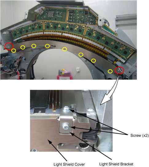
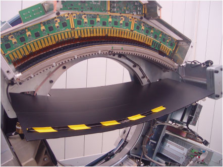
- Remove the light shield cover from the detector assy by unscrewing its eight screws (yellow circles). (See Figure 8)
- Put on gloves (supplied with system) before continuing to avoid introducing any contaminates on the detector module or around the detector collimator.
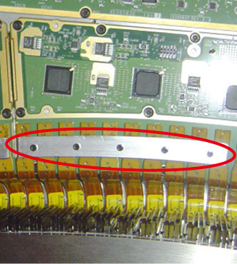
- Remove the plate for the relative flex cable connector from
the DIFB by unscrewing its five M3 Hex-socket screws.
Figure 9. Plate for Flex Cable
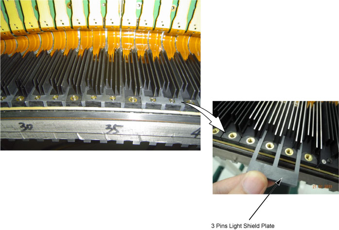
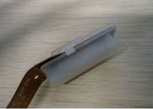
- Remove the light shield plate (2 pins or 3 pins) of related
module.
Figure 10. Light Shield Plate Removal (Example: 3 Pins)
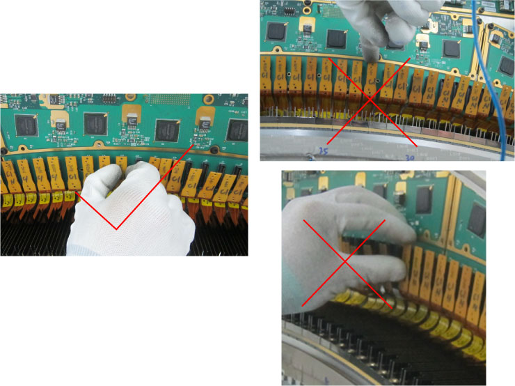
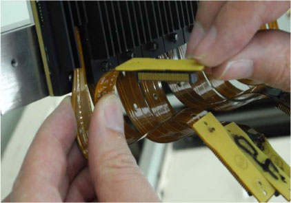
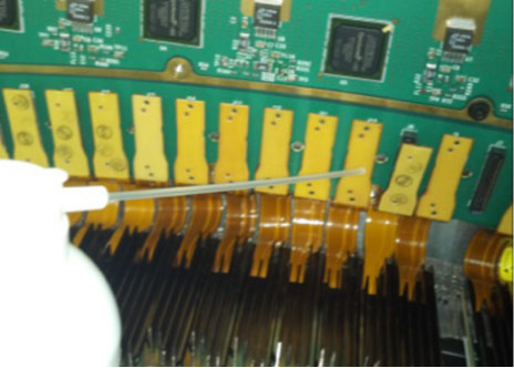
- Take off the flex cable from the DIFB by using correct way.
Correct way: Hold the edge of connector and unplug smoothly out, no tilt and shake.
Figure 11. Method for Disconnecting Flex Cables from the DIFBs
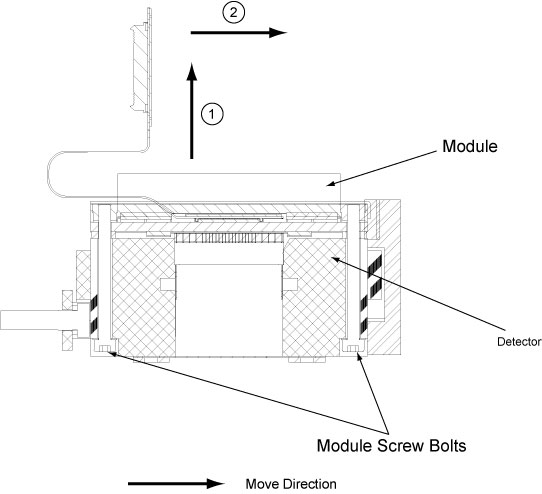
- Remove the two screw bolts (M4x45) from the defective module.
Figure 12. Module Screws Removal
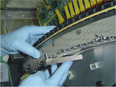
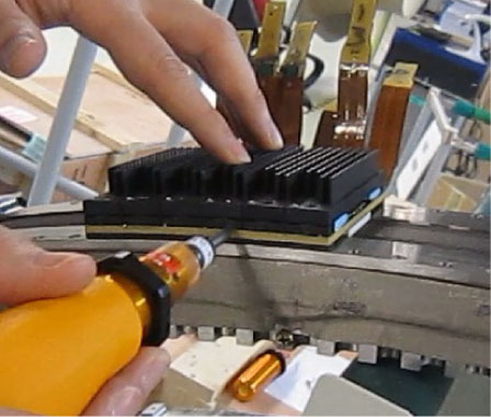
- Insert the seating tool into screw holes before taking off the
module from the detector.
Figure 13. Seating Tool Setting
- Take the defective module off in vertical direction lightly
from the detector, then take away the seating tool and move the module
out in horizontal direction.
Figure 14. Module Removal
5 FRDM Installation
Procedure
- Take the new module from the FRU kit, and remove the protective
harness from the flex cable connector.
- Bend the flex cable to the certain shape shown as below.note:
Softly bend the flex cable and avoid sharp angle, otherwise the flex cable may cause permanent damage.
Figure 15. Bend Flex Cable
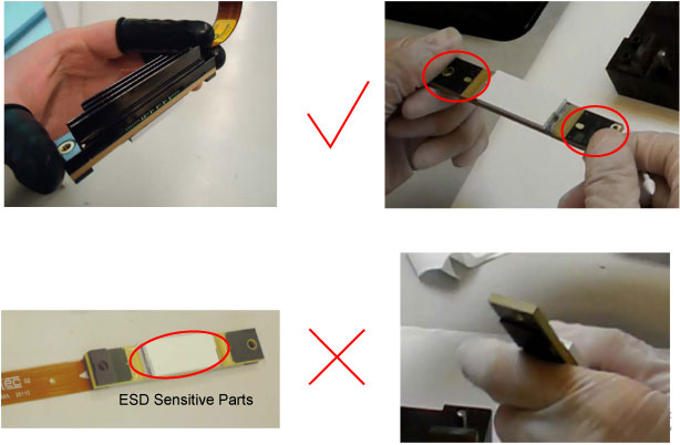
 note:
note:Because the module is made of ESD sensitive parts, so don’t touch module pack, and handle module only by two sides of its substrate.
Figure 16. Handle Module
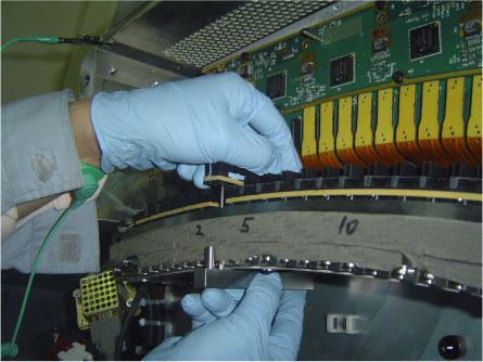
- Re-insert the seating tool into screw holes, then carefully
put the new module into location according to localization of the
seating tool. DON’T TILT OR SHAKE AROUND.
Figure 17. Locate Module 1
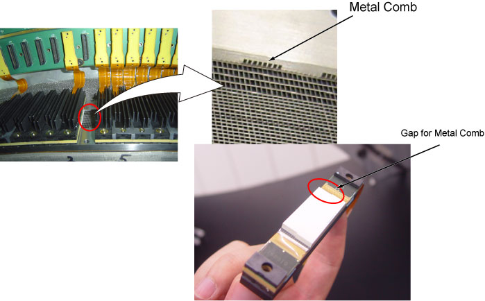
 note:
note:Collimator has very accurate metal comb, always be careful to avoid damaging, bending, etc.
Make sure the module does not press metal comb during positioning the module.
Figure 18. Locate Module 2
- Feel the module surface to check whether they are flat compared
with around modules.
If there is any unevenness, re-seat the module again until all flat.
- Don’t shake module and keep fixing, then take away the seating tool.
- Keep pressing down and inwards module, then secure the two screw bolts slightly.
- Make sure the edge is flat with others. you can click the edge
slightly, and keep pressing down and inwards a little.
If there is any unevenness, re-seat the module again.
note:Don’t push the edge, only knock it slightly a few times until you feel it can’t be moved easily.
Figure 19. Locate Module 3
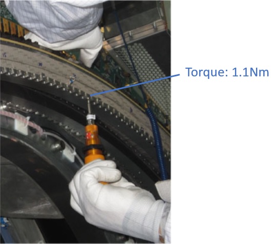
- Fix the outer screw bolt a little, then the inner one in turn, and the outer one again. Repeat this procedure until both are fixed. (Torque: 1.1 N.m)
Figure 20. Apply Torque for Screw Bolt

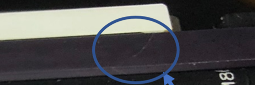
 caution
Figure 21. Crack in Substrate
- Clean the flex cable connector by the aero-duster before connecting,
then connect it to the DIFB.
Figure 22. Clean Flex Cable Connector
- Insert the light shield plate removed in Step 6.
- Turn power on to the gantry to perform static X-Ray Off, make
sure the cable is correctly connected. If cable is not connected well,
MSD may have shown in Figure 23.
Figure 23. DDC curve with Bad cable connection
- Secure the plate to the DIFB for the flex cable connector fixing.
(Torque: 1.0 N.m)note:
High torque will loose the screw beneath DIFB board.
- Install the light shield cover being careful around thermistor wires by using torx head screws. (Torque: 2.5N.m)
6 Detector testing
|
|
Procedure
- Install the air plenum as shown in Vyper Plenum ASM Removal.
- Turn power on to the system to perform detector testing.
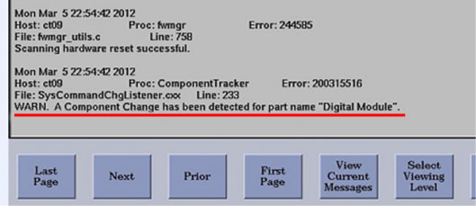
- CT log will report the new module after replacement.
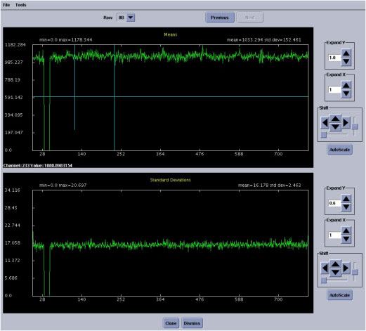
- Perform FRDM and check curve.
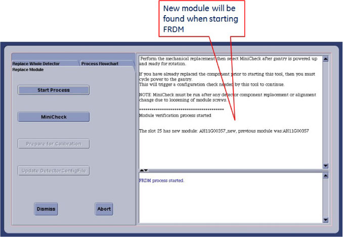
- Mini-check function will calculate the module bias.
- If FRDM check does not pass, loose the module screw bolts and redo Step 7 and Step 8, then repeat FRDM check.
- After the alignment plot is closed (not minimized, must exit
the window) the DASTools GUI will automatically show up. From the DASTools interface run the following rotating tests.
- Select and Run mA Ratio Test (creates/updates the bad channel map)
- Select and Run the Auto Test from DAS Tools.
If all the checks pass continue with the next step. If anything fails, troubleshoot per the failed test.
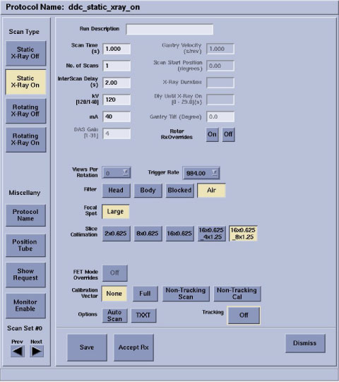
- Perform Diagnostics –> Diagnostic
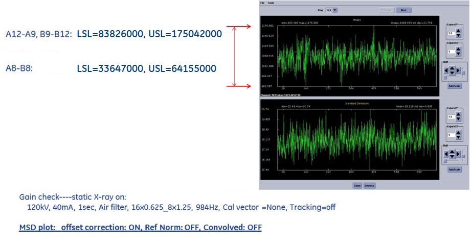
Data Collection (DDC). Select below protocol: 120kV, 40mA, 1sec, Air filter, 16x0.625_8x1.25
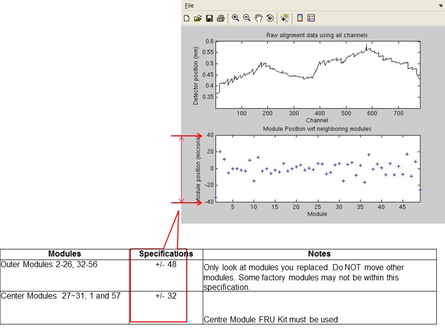
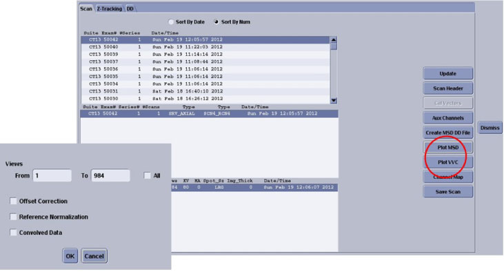
- Perform Image Quality –> Scan
Analysis and generate the MSD file.
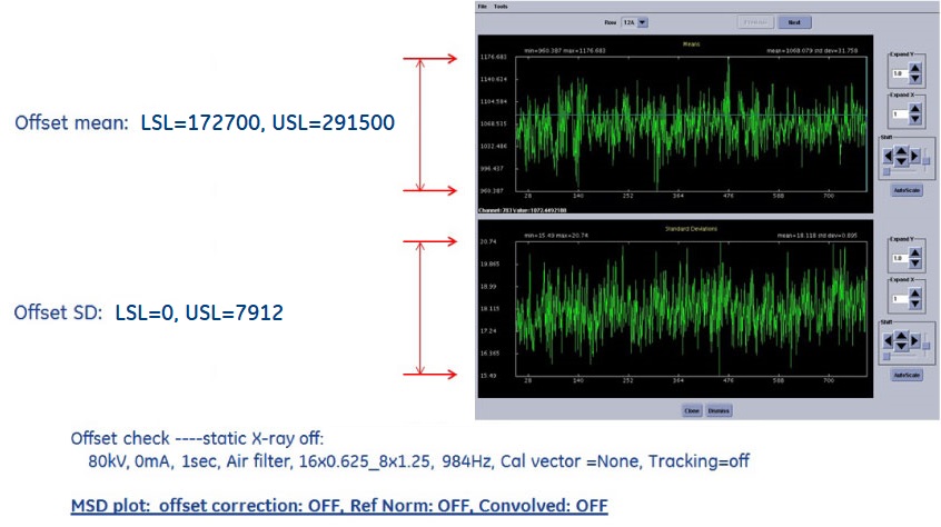
- Check the curve and confirm all are in specs.
7 Gantry Reassembly
Install all gantry covers remembering to enable Axial Drive just before installing gantry right side cover.
Refer to Replacement → Gantry → Enclosure → (Cover Removal Procedures).
8 System Calibration
Procedure
- The user message log will indicate when the detector temperature has reached specification by a message indicating the detector has returned to normal temperature. You may have to wait for up to 45 minutes from the time the detector was powered on to allow detector to warm up prior to starting the calibration process. Calibrations are not allowed to start until the detector reaches proper temperature.
- From the FRDM Process Tool currently open
at the console select Prep for Calibrations.
A test will be run prior to calibrations that will check for center artifacts. This test is specific for center module (27-31) and will only be run when a center module is replaced to make sure no center module artifacts have been introduced due to accidental movement of a center module. Acknowledge that the system is ready for gantry rotation and then press the Start Scan hard key when indicated to run the test.
The Center module test will report a Pass or Fail. If the center check fails, the center module just inserted is not compatible with the other center modules and needs to be replaced. A failure will not be a common occurrence since the system has been updated with a new calibration vector to account for center module variations. Only significant module issues should cause a failure. Potential IQ issues for a failing module include all center related artifacts including center spot and smudge. If the test passes, continue with calibrations.
- Perform a Collimator Cal.
- Perform a full Detailed Cal.
- Perform a Fast Cal.
- Perform a CT Number Adjustment (suggest).
9 Finalization
Procedure
- Perform the Quality Assurance Test.
- From the FRDM Process Tool currently open at the console select Update Detector Configuration when the system is ready for customer operation. This will read and update the new detector configuration and perform any background cleanup of temporary software files created by the tool during the replacement process.
- Perform a Save State to save the new calibrations.
- Tools Return Policy: Re-package all provided service tools, in the original packages, and place into the FRU shipping container.
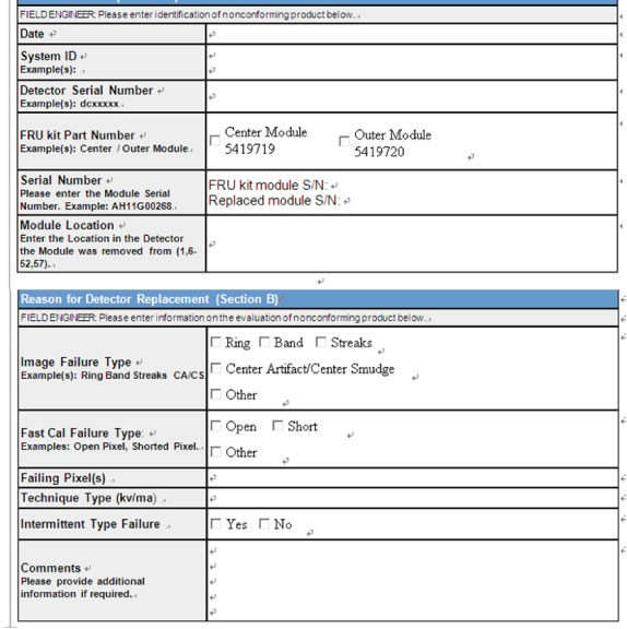
- Fill in the return form and send back for analysis.