- Topic ID: id_11038727
- Version: 3.0
- Date: Jun 10, 2020 2:30:21 AM
Auxiliary Assembly Replacement
Prerequisites
This procedure describes how to:
-
Replace Auxiliary Assembly
-
Run application scan(s) to verify system operation
1 Auxiliary Assembly Removal
Procedure
 danger
- Move table to its lowest elevation.
- Remove power to the gantry using proper Lockout/Tagout procedures.
- Remove side top and front gantry covers.
- Turn OFF all 3 switches (Axial Drive, HVDC, 120VAC) on the Service Switch Panel.
- Remove power at main disconnect (A1) panel. Use proper Lockout/Tagout procedures.
- Rotate the Gantry until the Auxiliary Assy reaches the 3 o’clock position.
- Engage gantry rotational lock.
- Cut any tie-wraps holding the cables to the Auxiliary Box
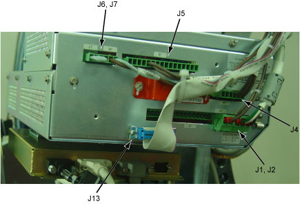
- Disconnect the following cable connector from the Auxiliary
Box.
-
J1/J2 Connector (<-> Tube/Power Unit)
-
J4 Connector (<-> Power Unit)
-
J5 Connector (<-> Power Unit)
-
J6/J7 Connector (<-> Power I/F Board)
-
J13 Connector (<-> Power Unit)
Figure 1. Auxiliary Box Cable Connections
-
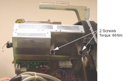
- Unscrew the 2 screws, and remove the auxiliary box from the
Gantry.
Figure 2. Auxiliary Box Removal
2 Auxiliary Box Installation
Procedure
- Ensure that Lockout/Tagout procedure has been applied, and that gantry power is removed.
- Ensure that gantry rotational lock is engaged and gantry does not rotate by attempting to rotate gantry by hand.
- Place the new auxiliary box.
- Torque the two screws to the following pre-load value.
- Torque the two screws to the following final value.
- Torque the two screws to the following pre-load value.
- Connect the all cable connectors of the Fan Inverter.
- Fasten the cables to the auxiliary box using tie-wraps.
3 Finalization
Procedure
- Perform Gantry Rotation Safety Check.
- Perform Gantry Balance Procedure.
- Perform Meter Verification.
- Perform HV Tank Feedback Resistor Verification.
- Perform Filament Calibration.
- Perform HHS Scan (Gen).
- Perform System Scanning Test.
- Perform Quality Assurance Test.