- Topic ID: id_23554155
- Version: 3.0
- Date: Nov 27, 2020 2:03:44 AM
Varian Respiratory Option Install
Prerequisites
Overview
This document defines how to install the Respiratory gated feature using the Varian gating system option (Remote Patient Monitoring or RPM system E8819KA).
All the necessary gantry internal gating hardware and cabling has been installed at the factory to accommodate two gating system installation configurations:
Effectivity
Used with the following Gating Options:
-
Advantage 4D Respiratory Gating Option
-
Prospective Respiratory Gating Option
-
(For PET/CT) Motion Match Option (called MotionFreeApps on options menu)
1 Pre-Installation Requirement Checks for Customer/Facilities
All pre-installation items must be completed by the customer's facilities department, general contractor or sub-contractor prior to the scheduled RPM installation date.
Procedure
-
Power Supply Module is mounted, plugged
into an outlet within 6 feet (2 meters) of the power supply and placed
near coax cable conduit.
-
Power Supply Module mounting options:
-
Direct to wall.
-
Inside a custom built wall storage cabinet.
-
Above false ceiling (as shown in the Varian IDP).
-
-
If Power Supply Module is placed above the ceiling, then it must be plugged into a switched outlet that is within 6 feet (2 meters) of the power supply.
-
If Power Supply Module is installed directly to the wall, then it must be reachable by technologist.
-
Power Supply Module is supplied in Varian Kit.
-
-
Camera Storage Hanger is firmly mounted.
-
Determine placement and secure to wall or inside the custom built wall storage cabinet.
-
Camera storage hanger is supplied in Varian Kit.
-
-
1 inch (25mm) Conduit is routed from
RPM Computer Console area to RPM Power Supply Module, not to exceed
75 feet (23 meters).
-
Depending on room design/layout, a raceway may be substituted for the conduit.
-
Customer’s responsibility to supply.
-
-
Coax Camera Cable is routed between the
PET/CT scanner and control room.
-
Run cable through conduit.
-
Cable is supplied in Varian kit.
-
- 1 1/2 inch (38mm) Conduit is routed from the Power Supply Module to Curtain Rail location, not to exceed 20 feet (6 meters). (Customer’s responsibility to supply.)
-
Standard Hospital Curtain Rail is mounted
between the storage hanger and the foot of the table following the
plane of the table movement.
-
Provides a way to manage the cable when the camera is attached to the table.
-
Used to protect the cable from potential damage and possible risk from invalidating the warranty.
-
Customer’s responsibility to supply.
-
- Live Network Port is available in each console area near RPM workstation and Static IP Address.
- By company policy, GE field representatives are not authorized to handle any of the pre-installation items.
- Ensure that a customer’s IT support representative will
be available during the day of the installation.
-
Customer’s IT support will provide access into the network server.
-
GE field representative will set-up SmartConnect.
-
- System security requirements for gating.
-
Do not add any other software to the RPM workstation.
-
No other applications have been validated.
-
RPM workstation will not accept OS patches and Anti-virus updates (refer to Varian Anti-Virus policy).
-
An electrician must attach conduits for the power and signal cables as required to meet local construction codes.
2 Getting Started
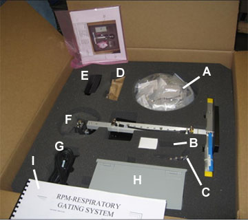
2.1 Verify Kit Parts
Procedure
- Verify that all of the following items are in the kit per table below.
- If any of these items are missing, contact Varian at 1-888-VARIAN5.
Figure 1. RPM Respiratory Gating Kit
2.2 Typical and Alternate Configurations
Procedure
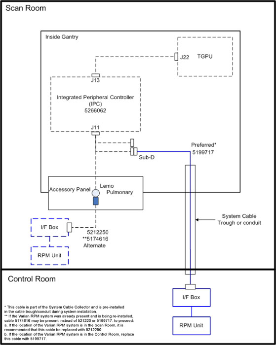
- (For Typical Gating system installed in Control Room) The respiratory trigger cable is part of the system installation cable set and has been installed in the cable trough or conduit between the Scan Room and Control Room during the system installation process to accommodate a typical Control Room respiratory gating system installation.
- (For Alternate Gating system installed in Scan Room) Some customers may have existing Respiratory systems and may still use the alternate cable 5212250. If the customer prefers an “In Scan Room” installation (Gating system located near the gantry) then cable 5199717 will not be used and the gating system will be directly connected to the Accessories Panel on the side of the gantry with this existing alternate cable 5212250.
-
(For Previously Installed Respiratory System) If the customer has previously purchased a Respiratory system and
this Respiratory system is being re-installed as part of a system
installation, cable 5174616, 5212250, or 5263547 may be present on
site.
-
If the respiratory gating computer system is located in the Control Room, remove and discard cable 5174616, 5212250, or 5263547 from the cable trough/conduit between the Scan Room and Control Room and use 5199717, which is part of the system cable collector.
-
If the respiratory gating computer system is located in the Scan Room and cable 5174616 is being used, discard this cable and replace it with 5212250 or 5212250-2 refer to Table 1 for desired cable length.
-
If the respiratory gating computer system is located in the Scan Room and cable 5212250 or 5212250-2 is currently on site, cable 5199717 will be unused (located in the cable trough/conduit between Scan Room and Control Room). The customer may continue to use cable 5212250 or 5212250-2.
-
If the respiratory gating computer system is located in the Scan Room and the customer prefers a shorter cable, replace cable 5212250 with 5212250-2 Table 5.
-
- Varian Camera Mounting Configurations:
-
PET System ONLY: If the RPM (Remote Patient Monitoring) camera is to be mounted to the cradle using the Varian Camera Mount Bracket kit Catalog # E8819HB, this bracket must be installed prior to starting this procedure. Refer to the installation instructions included with that option.
-
If the RPM (Remote Patient Monitoring) camera is to be installed on the table cradle using one of the Flat Top Table Option kits then this option must be installed prior to starting this procedure. Refer to the installation instructions included with that option.
-
All other camera mount configurations must be coordinated with the customer on a case-by-case basis and may require a structural Engineer. These may include wall mounts, ceiling mounts etc. For a successful installation, clarify the mounting configuration before proceeding with this procedure.
-
3 Mechanical Installation
3.1 Install Workstation and Remaining Cables
Procedure
- Locate and install the workstation at customer’s preferred location.
- Connect cablesFigure 2 or Figure 4.
Figure 2. Typical Cable Connections
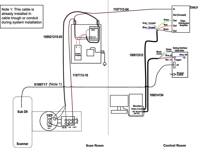 note:
note:For a larger version of the illustration above, click on the pdf icon below:
Figure 3. Typical Cable Connections
3893539.pdfFigure 4. Alternate cable Connections
3.2 Camera and Bracket Subassembly Installation
Procedure
- Mount the camera and bracket subassembly on the table using
one of the following methods:
-
PET System ONLY: If the RPM (Remote Patient Monitoring) camera is to be mounted to the cradle using the Varian Camera Mount Bracket kit Catalog # E8819HB, refer to the installation instructions included with that option.
-
If the RPM (Remote Patient Monitoring) camera is to be installed on the table cradle using one of the Flat Top Table Option kits, refer to the installation instructions included with that option.
-
All other camera mount configurations must be coordinated with the customer on a case-by-case basis and may require a structural Engineer. These may include wall mounts, ceiling mounts etc.
-
- Move the table top so the camera is as far as possible from the power supply module. This is to ensure the cable, when installed in the following steps, is not overstretched at any point along its length.
- Connect cable (P/N 100021215) to the unique connectors on the camera/bracket subassembly: LCD monitor power, infrared light source power, and camera power Figure 2.
- Fasten the cable to the camera bracket using cable ties.
- Suspend the cable from the curtain rail to meet these requirements
(if customer supplied):
- Cable must travel smoothly from one end of the table travel to the other.
- Cable must safely clear all personnel when the camera and bracket subassembly is installed on the table.
- Cable must be out of the way when the camera and bracket subassembly is stored on the wall.
- Connect the cable to the power supply module:
- Connect the spade lugs of the infrared illuminator ring and the small video display power cables to the top of the power supply in the power supply module, paying close attention to the + and - marking on each cable.
- Connect the camera cable to the TRG A/VD IN connector on the junction box in the power supply module.
- Connect the BNC cable to the VIDEO OUT connector on the junction box in the power supply module.
3.3 Connecting the Interface to the Scanner
Procedure
- Connect the Video Media Switch - supplied cable (P/N 100014154) to the Respiratory Gating Interface box.
- Connect the other end of the cable to the I/O board on the RPM workstation.
- The RPM Respiratory Gating Interface box must be placed on the
CT or PET console table, within 6 feet (1.8m) of the RPM workstation,
and within easy reach of the user to allow a quick disconnect in the
unlikely event of a hazardous situation.
To connect the RPM Respiratory Gating Interface box to the CT or PET scanner:
-
Connect cable (P/N 1107113) to the IN connector on the video distribution amplifier (VDA) (labeled as VAC).
-
Connect cable (P/N 100013312) between the frame grabber board on the RPM workstation and to the OUT 1, 2, and 3 connectors on the VDA.
-
Use self-adhesive hook-and-loop fasteners to position the VDA on top of the workstation or in another convenient location.
-
3.4 Setup the Breathing Phantom and Varian Camera
Procedure
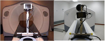
- Mount the camera so that it is facing the patient opening of
the gantry Figure 5.
– Attach the camera to the Flat Table Top cradle (if present).
OR
– Use one of the optional camera mounts at the foot of the table (end furthest from the gantry).
Figure 5. Typical Camera Mounts (Left: RT Flat Table Top Mount; Right: Cradle Mount)
 note:
note:Ambient light can disrupt the camera tracking. Reduce the lighting if necessary.
- Verify that the RPM cable and equipment is connected and camera power is ON.
- Install batteries in the Breathing Phantom (Batteries are not
included).
Figure 6. Breathing Phantom and Marker Block Setup
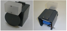
- Tape the Marker Block to the plastic tab on the Breathing Phantom Figure 6.
- The Marker Block should be taped to the Breathing Phantom so that the two dots face the Varian Camera. The rotation of the wheel moves the plastic tab and Marker Block up and down during rotation. (The camera must see the two dots moving up and down).
- Place the RPM Breathing Phantom on the table, near the table
head holder end of the cradle Figure 7.
Figure 7. Camera and Phantom Setup
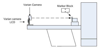
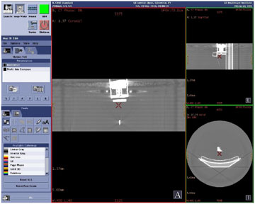
- Adjust camera head and Breathing Phantom so that the two dots
from the Marker Block appear in the camera's LCD display window Figure 7 and Figure 8. If necessary,
adjust room lighting to the customers scanning environment.
Figure 8. Camera Dots in LCD FOV
 note:
note:The Camera is very sensitive. The Marker Block should face camera and not tilted at an angle that exceeds 25 degrees, with relationship to the camera face. Minor adjustments should be made to ensure the two dots clearly show up in the Varian Camera LCD display window.
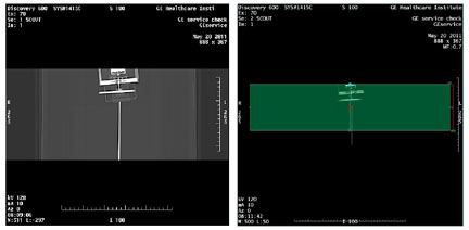
- Verify that the two dots appear in the center of the camera
LCD and not outside the LCD FOV over the entire length of the Table/Cradle
travel. Adjust the Breathing Phantom or camera if required Figure 7.
- Measure the distance from the camera to the Marker Block. Write this measurement down as it will be needed later in the setup.
- Aim the camera at the Marker Block.
- Open the Aperture all the way.
- Focus the Camera.
- Close Aperture until background disappears from view and only the two dots remain Figure 8.
4 Varian Computer Power Up and Configuration
Procedure
- Log in to Windows on the Varian RPM computer.
- Windows XP or Windows 2000
Enter Username: AdminEnter (case sensitive) (Default).
Enter the password: VARIAN01Enter (all uppercase) (Default).
note:Username and Password may vary site to site. Consult with site personnel.
- Windows 7
Enter Username: RPMAdminEnter (case sensitive) (Default).
Enter the password: RPM$Adm1nEnter (case sensitive) (Default).
note:Username and Password may vary site to site. Consult with site personnel.
note:The password for deleting patients (and also performing other settings) is: RespGate (case sensitive).
- Windows XP or Windows 2000
- Double-click the RPM Gating System icon to launch the program. The RPM Respiratory System Gating main window will appear.
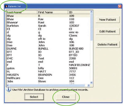
- On the Patient List window, select Close. See Figure 9.
Figure 9. Patient List
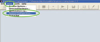
- Select . See Figure 10.
Figure 10. View / System Configuration Screen
- Select General tab Figure 11. Enter Database
and Archive database locations. Obtained from the customer.
Figure 11. System Configuration: General Tab Screen
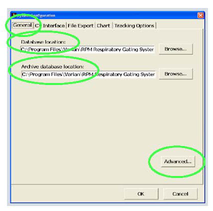
- Click Advanced. See Figure 11. A password required screen will pop up. Enter RespGate and press ENTER.
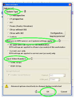
- The Advanced Options screen is displayed.
Verify defaults shown in Figure 12.
- System Type - (Default setting shown).
- Changes in RPM session - (Default setting shown).
- Input Video Standard - (Default setting shown).
- Click OK.
Figure 12. Advanced Options Screen
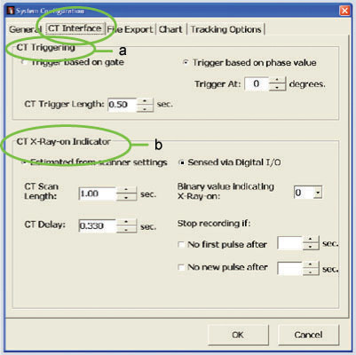
- Click CT Interface tab. Verify defaults
shown in Figure 13.
- CT Triggering - (Default setting shown).
- CT X-Ray-on Indicator - (Default setting shown).
Figure 13. CT Interface Tab Screen
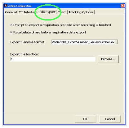
- Click File Export tab. Verify defaults
shown in Figure 14.
Figure 14. File Export Tab Screen
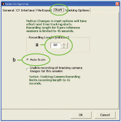
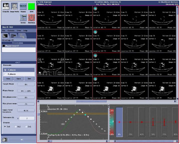
- Click Chart tab.
- Recording Length - 30 is typical.
- Check Auto Scale.
Figure 15. Chart Tab Screen
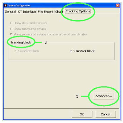
- Click Tracking Options tab. See Figure 16.
- Tracking block - This selection is already set to the default of "2 marker block".
- Click Advanced.
Figure 16. Tracking Options Tab Screen
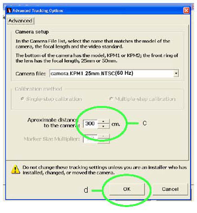
- Approximate distance to the camera - See Figure 17. Enter distance measured in Step 8.a.
- Click OK.
- Click OK.
Figure 17. Advanced Tab Screen
- Enter IP Address in the Varian computer as follows:
- On the Varian computer click .
- Double click Network Connections.
- Right click on .
- In the Varian Network Properties window select the General tab.
- Under This connection uses the following items: select Internet Protocol, (TCP/IP).
- Click Properties.
- Select Use the following IP Address: and enter your hospital IP information.
5 GE Scanner Software Installation
5.1 Install Respiratory Option (CT Systems)
Software version 08BW44.1 or later is required for installation of PRG Option Key.
Procedure
- Install the Respiratory Gating option software using the option key B7022RT.
- Work with CT Scanner Technologist or CT Applications Specialist to perform respiratory gating scans. Refer to the operators manual (Learning and Reference Guide), Respiratory triggering chapter for details.
5.2 Install Respiratory Option (PET Systems)
Enabling the Gating function requires a Motion Match Option key P5054K (called MotionFreeApps on options menu).
Procedure
- To proceed:
- If PET Motion Match Option has not been installed, complete this section.
- If PET Motion Match Option has been installed, skip this section and proceed to Respiratory Gating Hardware Function Check.
- Insert the Motion Match Options media disk in the USB Tower
DVD drive.note:
(For GE Healthcare personnel only) Options must be loaded before protocols. If you do not have the Options media disk (key), then you can use the eLicense feature. Follow this link to the eLicense page: http://elicense.gehealthcare.com/elicense/
- With Applications up, select the [Service] icon.
- Click on CT radio button.
- Select Configuration.
- Select Install Options. The Example Software Options screen appears.
- Select Install. The Select mechanism box appears.
- Select Permanent. The Select Device box appears.
- Select MEDIA. The SwOptions MEDIA box appears.
- Select OK for DVD insertion.
- Software options available for installation are displayed on the options screen.
- Install the MotionFreeApps option.
- Select Quit to exit the window when the process is complete.
- Select Quit again to exit Install Options window.
- A window appears displaying the message: Application should be ShutDown and ReStarted for installed/removed Options to take effect.
- Select OK.
- Press the button on the DVD-RAM drive on USB Tower to eject the option DVD.
- Close the Service Desktop window in the upper left corner of the screen.
- If the language was modified via a reconfig for options, re-perform the reconfig process at this time to re-select the preferred language.
- Shut down and restart Applications.
6 Respiratory Gating Hardware Function Check
This section uses the RPM system to generate a simulated Respiratory Trigger, which will allow for a Functional Test of the Respiratory Option.
-
Refer to the Varian-supplied manuals for the installation and use of the Varian RPM unit and camera.
-
Refer to the attached appendix for general references that may help in the final setup and testing of the unit.
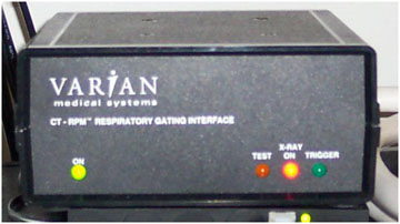
6.1 Basic Varian RPM Hardware Check
Procedure
- Make sure the Varian camera support equipment is connected and powered up, and that the Varian RPM Computer is powered up with Microsoft Windows running. (RPM software does not need to be running).
- Turn Varian camera power ON.
- Turn Varian I/F box ON.
- Remove, or DO NOT connect, gating cable 5199717 or 5212250 to the Varian I/F box J4. (Make sure this cable is disconnected from the system.)
- On the Varian I/F box, verify the following:
- The green “Power” indicator is ON.
- The red “X-Ray ON” indicator is ON.
- The “Test” indicator is OFF.
- The “Trigger” indicator is OFF.
If one or more of these conditions are not met, there is a problem with the Varian RPM equipment. Troubleshoot the issue or contact Varian to resolve the problem.
6.2 Respiratory Gating Signal and Camera/Phantom Tracking Test
Procedure
- Connect the RPM Gantry Cable (5199717 or 5212250) to Varian I/F box Sub-D J4. Verify that the “X-Ray ON” indicator on the Varian I/F box is OFF.
- Turn ON the Breathing Phantom. The Marker Block (Dots) will start moving up and down in the camera FOV.
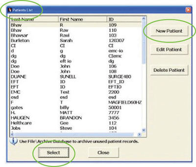
- Select
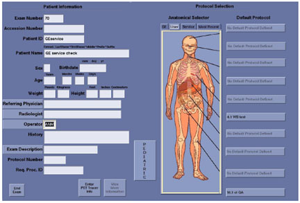
- On the Patient List window click New Patient. See Figure 18.
Figure 18. Patient List Window
 note:
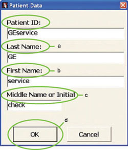
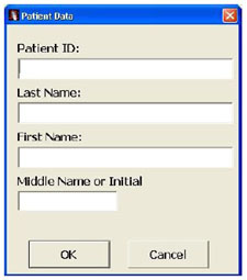
note:Patient ID must be unique. Name field information may be defined as desired. The values shown are suggested defaults.
- Enter Patient ID: GEservice
- Complete the following fields Figure 19:
- Enter Last Name: GE
- Enter First Name: service
- Enter Middle Name: check
- Click OK
Figure 19. Patient Data Window
- On the Patient List window, select patient ID just created: GEservice.
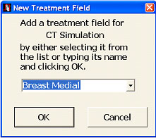
- Click Select. A New Treatment
Field window will appear Figure 20.
- Select an existing treatment field from the list: Breast Medial (Default).
- Click OK. An RPM Respiratory Gating System window will appear.
- Click Yes (Create Reference Session). The Main RPM window will now appear.
Figure 20. New Treatment Field
- If not checked, click Auto Scale on the main window.
- Click View.
- Click Session Options.
- Verify Options setting on Gating Tab.
- Verify Normal Breathing Predictive Filter Threshold parameter is set to 20.
- Verify Audio settings on the Audio Tab. Under Automatic Audio
Instructions window:
- Set Automatic Audio Instructions to Enable for sound, or Disable for no sound.
- Set Inhale and Exhale Periods to: (Automatically)
tied to sensed intervals.note:
No change to Inhale and Exhale periods. They remain at a value of 0.0.
- Click OK to accept the values.
- From the Navigation bar, click Record. The display will start mapping the motion and the Enable gating
Button becomes active.note:
The application will begin to track the motion of the dots. Wait until the progress bar in the top left corner of the image goes to one block on the left of the bar.
- Click Enable Gating from the navigation bar to start simulated triggers.
- Verify that the Green “Trigger” Indicator on the Varian I/F box flashes slowly.
- Click Stop. A RPM Respiratory Gating window appears.
- Click Cancel. Do not enter patient information.
- Click . A RPM Respiratory Gating window appears.
- Click NO. Do not save motion data.
- Turn the Breathing Phantom OFF.
If not done previously, perform Setup the Breathing Phantom and Varian Camera before starting the Tracking Test.
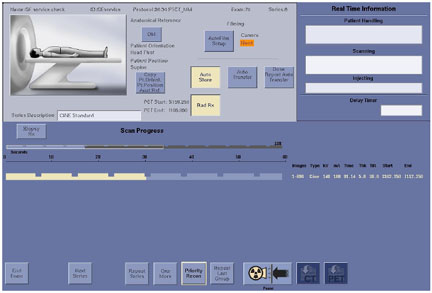
6.3 X-Ray-ON Signal Functional Test
Procedure
- Make sure that the RPM Gating cable (5199717 or 5212250) is connected to the Varian I/F box (9-pin Sub-D-J4).
- Make sure the other end of the RPM Gating cable is connected to the Respiratory Gating port at the scanner.
- At the console select Exam Rx icon on Display Screen, then click New Patient on Scan Screen.
- Type Patient ID: Service 1.
- Type Patient Name: RPM Check.
- Click GE (Anatomical Selector) and then prescribe/select a Scout Scan [PTCT_ET_2D , [PTCT_ET]or equivalent to setup a scan.
- In the scan room, set up a phantom and establish a Landmark.note:
For PET/CT system use CT Table Base Position.
- Install the phantom holder on the cradle at the cradle end closest to gantry.
- Place a phantom on the phantom holder.
- Press Alignment Light to turn ON the Laser Alignment Lights.
- Move the phantom into the Laser Alignment Lights.note:
Actual alignment light location on the phantom is not critical.
- Press Landmark to enable Landmark.
- Press Alignment Light to turn OFF the Laser Alignment Lights.
- At the console, enter a scan length for Scout and Acquisition:
- Start: S100.00
- End: I100.00
- Verify at the Varian I/F box that the Green “Power” indicator is ON.
- At the scanner display, click Confirm.
- Press Move to scan.
- While looking at the Varian I/F box “X-Ray-ON” indicator, press Start Scan.
- Verify that the red “X-Ray-ON” indicator illuminated for the duration of the scan.
- Press End Exam.
- If the “X-Ray-ON” light did NOT light up during scan, troubleshoot the problem. If the “X-Ray-ON” light was seen, at the gantry drive the cradle out of scanner until it stops.
- Remove the phantom.
- Remove the phantom holder.
- Remove the Breathing Phantom and store in the service cabinet.
- Turn the camera OFF.
- Turn the Varian I/F box OFF.
- Remove the camera from the cradle and return to its wall storage position.
- If an external RPM Gating cable is being used, disconnect this cable from the IPC.
- Shutdown Windows: Click and then click OK.
- Turn the monitor OFF.
- If necessary, disconnect any cables.
- Re-install any system covers removed.
- Proceed at this time with further testing of the applications associated with the Respiratory Option by a qualified Applications personnel if desired.
7 Respiratory Gating System Level Check
7.1 At Scanner’s Table
Procedure
- Place two dot marker block on the plastic tab on the Breathing
Phantom. Location of the block should be at ~200mm from the RPM camera
so that the camera’s view is not obstructed when the table/cradle
is moved into the PET Gantry.
- Adjust RPM Camera lens so that only the reflective dots are
seen on the camera’s LCD.
- The RPM camera may need to be lowered to the lowest height on its support stand, so that the tracking block is seen when patient moves into the PET Gantry.
- Turn Breathing Phantom ON.
- Set an appropriate gantry landmark on the Phantom.
7.2 At Varian RPM Host Computer
Procedure
- Launch RPM software, create and select new patient. (Must match
Patient ID entered on Console’s Scan Screen, so the .vxp file
will match the correct series.)
- Create a New Treatment Field, and then create Reference
Session.
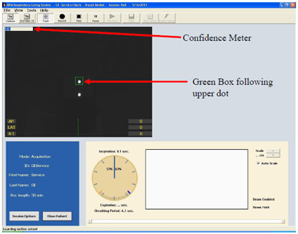
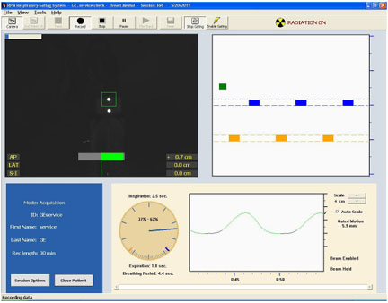
- Verify that the marker block is being tracked (up and down).
A green square, (on Varian 1.7v), around the uppermost white dot should
be visible. In the upper left corner of the black video window, the
confidence meter (blue blocks on progress bar) should reduce to less
than half of the meter when the system has established the breathing
pattern (~1 or 2 blocks remain on the left).
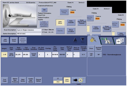
7.3 At Scanner’s Operator Console
Procedure
- Click New Patient on the Scan Screen;
create a Test Patient by entering patient’s name and ID (these
must match the entries on the RPM system).
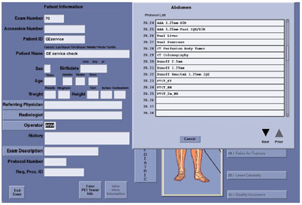
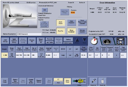
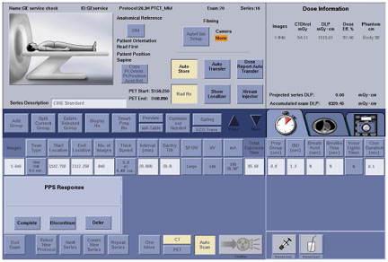
- Locate the “GE” Factory 4D Gating protocol under
the Abdomen body part (protocol titled PTCT_MM on
D600 series systems).
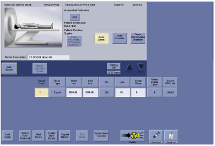
- Set Start Location to S100 and End Location to I100.
- Click Confirm to start the Scout scan
and verify phantoms position.
- Skip the WB Helical CTAC and WB PET, these scans do not need to be performed for this test. Proceed to the 4D Cine CT portion of the scan.
- For the 4D Cine CT: set Start Location to S100 and End Location to I100.
- Verify marker block is still being tracked on Varian’s RPM computer.
- On the Varian’s RPM main screen, click Record.
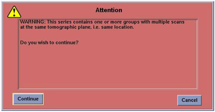
- Start the Cine CT scan. A warning message may pop up, click Continue.
- Verify that the RPM is working for CT: information should be
gathering on the Varian’s RPM computer’s main screen.
On the Varian’s I/F box, the X-Ray On LED should turn on during
X-Ray portions of the CT scans.
- When the CT scan has finished scanning, click Stop on the Varian’s RPM computer’s main screen.
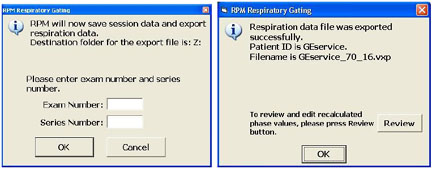
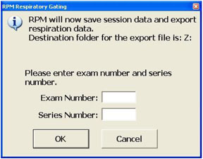
- Enter Exam Number and Series
Number of the test patient when prompted. Do this BEFORE
going on to the PET acquisition screen.
- Move on to the 4D PET series. Before starting the PET series
scan, on the RPM screen, Click Track, Record, and Enable Gating icons.
To verify that the RPM is working for PET, you should see information
gathering on the RPM screen.
- Start the PET scan, to verify that the RPM is working for PET
gating, the Trigger LED on the Varian’s I/F Box should flash
slowly. (The scan may be ended early if no activity is present).
- End the exam.
- On the RPM screen, click Stop.
- For PET acquisition, the RPM data does not need to be saved.
Click Cancel on the RPM Respiratory Gating
Window.
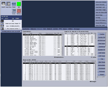
- Click Image Works icon on the Console’s
Display monitor and select the Cine CT series, (it will be listed
in the series # entered for this patient).
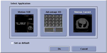
- Select MotionMatch option located in the selection bar on the right side of the Display monitor.
- Click Advantage 4D and click OK.
- If the data was entered correctly in the RPM, and the networking
between the console and the RPM computer is established (Samba installed),
the system should automatically highlight the correct Respiratory
Motion File.
- Select Motion Vue to verify that the
system has generated a good respiratory cine image set with no artifacts.
8 Appendix
8.1 Respiratory Option General Reference
Procedure
- The RPM acquisition software procedures can be found in the VARIAN Respiratory Gating System Version 1.7 (and forward) Installation Reference Guide. This document should accompany the RPM system. If you cannot find this manual contact Varian Support. (See Contacts.)
- Contacts: If you have failures or concerns with the outcomes from previous instructions that you cannot resolve with normal analysis and troubleshooting, refer to the Operations manual and the VARIAN Respiratory Gating System Version 1.7 (and forward) Installation Reference Guide, call GE Support, or call Varian (1-888-VARIAN5).
This section is for “General reference only”. Refer to the Varian Installation Manual for details and exact procedures for the operation of this unit.
8.2 Troubleshooting
Procedure
- If Basic Varian RPM Hardware Check fails the problem is with the Varian RPM hardware. Troubleshoot the Varian hardware only. Troubleshoot the Varian hardware problem or contact Varian.
- If Respiratory Gating Signal and Camera/Phantom Tracking Test fails the problem is with the Varian RPM hardware OR software. Troubleshoot the Varian hardware or software or contact Varian.
- If X-Ray-ON Signal Functional Test fails the problem is with the GE hardware (cabling or IPC board) or software on the scanner. Refer to the connection diagram (Figure 2 or Figure 4) to help troubleshoot the problem.
9 Finalization
Procedure
- If requested by the customer, perform Samba Installation. Loading and enabling Samba on the system allows for data to be quickly transferred between the Console and the Windows based system used by the Varian RPM software.
- Attach the rating plate on the rear of the OC (Operator's Console).
-
IMPORTANT: After completing
the installation, GE FE‘s must contact the Accessories Call
Center to report specific Varian System information.
-
The Accessories and Supplies Customer Service Team Information is:
-
The Varian information which needs to be provided to the Accessories Call Center is:
-
Serial Number
-
Date of Install
-
Facility Name and Address
-
Customer contact info (name, title, phone, e-mail)
-
GEHC FE Name and SSO#
-
-