- Topic ID: id_23554577
- Version: 1.0
- Date: Oct 9, 2018 1:41:11 PM
Heat Exchanger Pump Replacement
Prerequisites
Overview
Remove old pump and install new pump.
1 HX Pump Removal
Procedure
 warning
- Remove gantry power. Be certain to follow appropriate Lockout/Tagout procedures.
- Remove side and front gantry covers.
- Turn OFF all three switches (AXIAL DRIVE ENABLE, HVDC ENABLE, 120 VAC) on the Service Switch Panel.
- Rotate the gantry so the tube is at the 2 o'clock position.
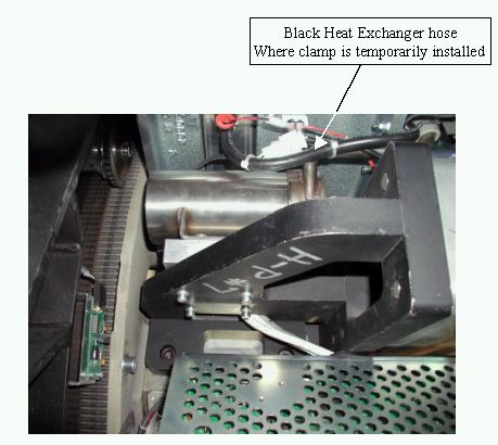
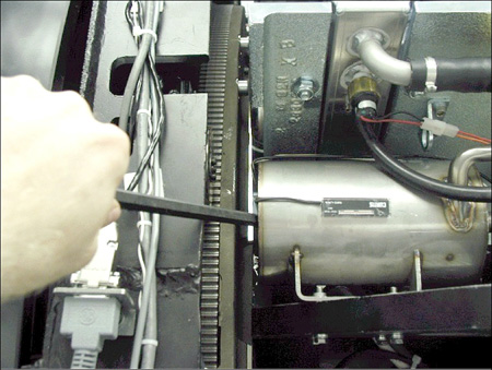
- If this system is a water-based cooled system, use the small
metal clamp (shipped with replacement part) to clamp off the black
heat exchanger hose (see Figure 1). This will prevent air ingestion
during the replacement process. The clamp should be installed finger-tight.
Oil-cooled systems skip this step.
Figure 1. HX Hose for clamping (water-based systems)
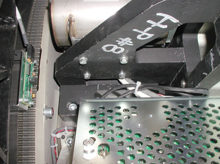
- Remove the 4 M6 screws (Figure 2) that mount the pump to the 107 weight stack bracket.
Figure 2. HX pump mounting M6 screws
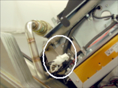
- Disconnect HX Pump 120 VAC at quick disconnect (see Figure 3).
- Remove two M6 nuts (shown in Figure 3 behind 120 VAC quick disconnect) for the pump's front mounting
plate.
Figure 3. 120VAC connector and front M6 nuts
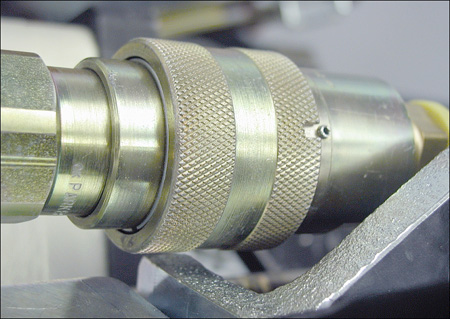
- Disconnect pump from heat exchanger at quick disconnect. Line
the slot up with the pin and push. The pump should easily disengage
(see Figure 4).
Figure 4. Align Pin and Slot
- Disconnect oil hose from X-Ray tube.
- Remove power interface board cover.
- Remove pump and hose from gantry.
2 HX Pump Installation
Procedure
- Rotate gantry so that X-Ray tube is at the 2 o’clock position.
- Connect pump to Heat Exchanger at quick disconnect. Make sure you align the pin and slot, then connect. See Figure 4 in HX Pump Removal.
- Route the hose to the tube. It routes underneath the Heat Exchanger shroud, but between the shroud and the clear plastic power interface board cover.
- Connect the pump hose to the tube. Secure the quick disconnect
using the safety locking mechanism. The torque spec. for the quick
disconnect safety mechanisms is 9.9 N-m (7.3 lb-ft, 88 lb-in, 101
kg-cm), however, if the locking mechanism rotates in relation to the
quick disconnect, tighten slowly until it does not do so.note:
Do not severely overtighten the M6 bolts. Doing so can cause the quick disconnects to leak.
- Reattach the Power Interface board cover.
- Connect pump 120 VAC connector.
- Unmount the ORP assembly by removing the two M12 bolts.
- Install the 4 M6 HX pump mounting screws. If you just replaced
the heat exchanger, it may require some force to realign the pump.
Using a lever helps but be sure not to damage the hour meter. See Figure 5.
Figure 5. Using lever to push pump around to align holes
- Attach the ORP assembly.
- Apply “pre-load” torque to the two M12 bolts:
- Apply final torque to the two M12 bolts:
- Apply “pre-load” torque to the two M12 bolts:
- Attach the two M6 nuts for the front pump.
3 Finalization
Procedure
- Ensure that proper torque specifications (see Torque Wrench Information) are followed for all fasteners.
- Ensure that clamp installed in Step 5 is removed, if applicable.
- (For Water-based Cooling System) Perform Heat Exchanger Purging (RT, Pro16 80kW).
- (For Oil-based Cooling Systems) Perform Hercules Coolant Flow Rate Measurement
- Run the appropriate Gantry Balance Procedure (e.g., go to ), to ensure that the gantry is safe for all rotation speeds.