- Topic ID: id_23554606
- Version: 2.0
- Date: Sep 26, 2020 10:11:51 PM
Hercules Coolant Flow Rate Measurement
Prerequisites
Overview
This procedure is used in concert with the Hercules Coolant Air Removal Procedure. This procedure checks for the proper flow rate in oil based coolant systems only. Low flow rate is an indicator of possible air in the coolant system or a faulty oil pump. Unusual Image Artifacts, tube over-temperature errors, or noisy oil pump are symptoms of flow related problems.
-
Coolant Air Removal Procedure
-
Heat Exchanger Compensation (Pro 16 & VCT)
-
Performed at PM
1 Frequently Asked Question(s)
Q: Can I use this tool and procedure for water-based coolant systems? A:NO. There is no procedure for water-based cooling systems. Introducing water-based coolant into this tool will require replacement of the Heat Exchanger, Oil Pump, and X-Ray Tube, as a complete set. Additionally, this tool will need to be scrapped. DO NOT contaminate with water-based coolants.
2 Procedure
Procedure
 caution
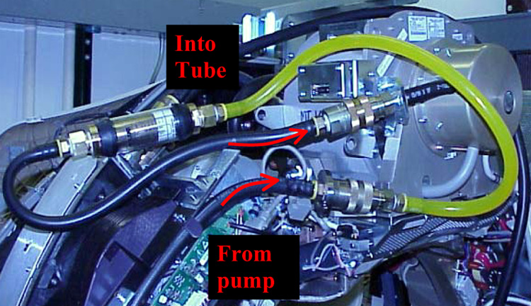
- Install the flow meter between the pump outlet and the tube inlet, as
shown.
Figure 1. Properly Installed Flow Meter
- Turn ON 120/240 Power on the Service Switch Board.
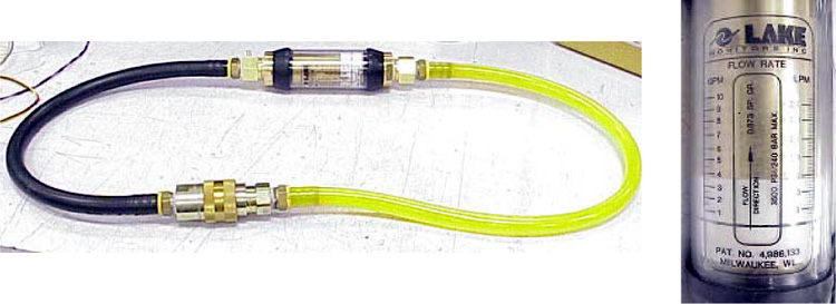
- Measure the oil flow rate, using the black line on the white indicator
and aligning it with the left hand scale of the flow meter.
- If the flow is equal to or more than 4.0 gpm, the flow is adequate.
- If the flow is less than 4.0 gpm, either the pump is malfunctioning, or there is air in the coolant system and the air removal process must be performed (see Hercules Coolant Air Removal Procedure).
Figure 2. Close-Up of Flow Meter
- Turn OFF 120/240 Power on the Service Switch Board.
- Remove the flow meter.
- Reconnect the quick disconnects, and tighten down the safety collars.
- Turn ON 120/240 Power on the Service Switch Board, and listen for oil flow at the pump.
 |
3 Finalization
Procedure
- If flow rate is correct, then no finalization is required.
- If flow rate is low, then perform the Hercules Coolant Air Removal Procedure