- Topic ID: id_23553955
- Version: 2.0
- Date: Sep 26, 2020 10:13:57 PM
Heat Exchanger Purging (RT, Pro 16 80kW)
Prerequisites
Overview
As a result of tube changes, or pump and heat exchanger changes, the Heat Exchanger's volume of coolant may change over time. In addition, it is possible to introduce air into the system which can cause problems due to lack of coolant flow and possible image artifacts. This procedure will both purge and compensate the tube coolant system. The procedure will remove air while leaving the proper amount of coolant in the heat exchanger. Note that this is only for Varian MCS 7079 tubes.Also note that as of November 01, 2011, if you require a purge kit it may be ordered from your respective Service Tool Depot. It must also be returned to the Service Tool Depot in it's original shipping container upon completion. Since there is a delay, please plan accordingly.
-
Power down gantry
-
Remove air from purge kit hoses
-
Attach purge kit between heat exchanger and x-ray tube
-
Turn on gantry AC power to enable heat exchanger pump
-
Keep power on until there is no milky colored liquid in purge bottle
-
Turn off gantry AC power and remove purge kit
-
Verify functionality of the Scanner
-
Safely restore system
MSDS Information for Propylene Glycol Coolant NOTE: We use two types of Propylene Glycol. The new kits contain food grade Propylene Glycol, which is clear, and the old kits contain non-food grade, which is yellow/green in color. Mixing the two types of Propylene Glycol has been deemed acceptable by the purge container OEM.
1 GANTRY PREP
Procedure
- Remove side and top gantry covers.
- Turn off all 3 service switches on the Service Switch Board (120 VAC, Axial Drive Enable, HVDC Enable).
- Remove front Gantry Cover. Cable disconnection is optional based on amount of space desired for procedure.
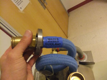
- Position Gantry such that quick disconnect on blue hose (between tube and Heat Exchanger) is easily accessible.
- Loosen Jam Nuts at bottom of quick disconnect bolts and remove the bolts. Do NOT disconnect the hose at this point.
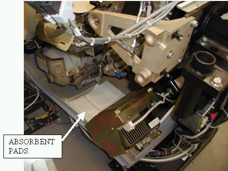
- Rotate the gantry such that the tube is between the 5 and 6
o’clock positions and place absorbent pads in base of cover
under the hose. Make certain that the connectors are not directly
above any electronic assemblies.
Figure 1. Absorbent pad placement
 caution
- Engage gantry rotational lock. Ensure that the gantry is locked by attempting to rotate the gantry by hand.
 |
2 PURGE BOTTLE PREP
Procedure
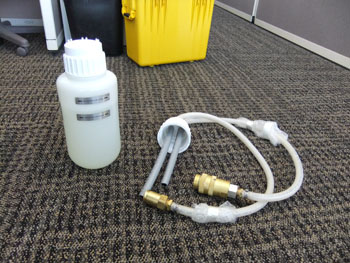
- Unpack the purge kit.
Figure 2. Original Purge Kit
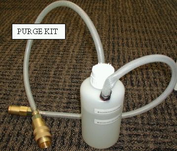
Figure 3. 2011 Purge Kit
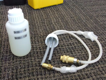
- On the 2011 Purge kit only, remove the bottle shipping cap and
replace with the procedure cap which has hoses attached.
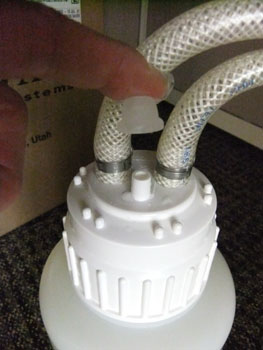
Figure 4. Quick Disconnects Connected Together
- .For both style purge kits, connect the quick disconnects on
the purge kit together. Refer to Illustration 4
Figure 5. Bottle with travel cap and procedure cap
- On the 2011 purge kit only, ensure that the rubber vent cover
cap is securely installed before turning the bottle upside down.
Figure 6. Procedure Cap Rubber Vent Cover
- On both style purge kits, turn the bottle upside down until all air in the hoses is removed. Verify that all air is removed from hoses by noting lack of bubbles flowing into the bottle.
- With the bottle still inverted, disconnect the hoses from each other.
- Return the bottle to the upright position.
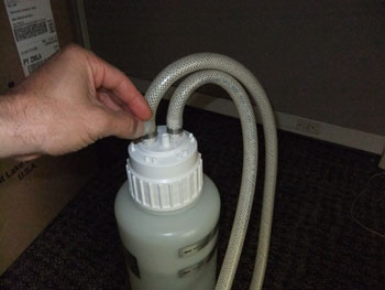
3 ATTACH PURGE KIT TO GANTRY
Procedure
- notice
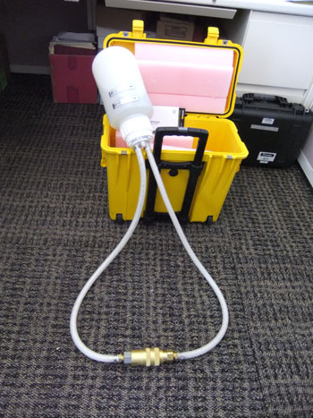
- Disconnect the hose between the heat exchanger and the tube.
- Connect the purge kit between the heat exchanger and the tube
and set it on absorbent pads on the floor.
Figure 8. Purge Kit Connected to Gantry
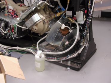
Figure 9. 2011 Bottle connected to gantry
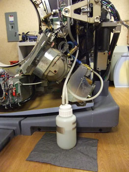
- On the 2011 purge kit only, remove the rubber vent cover from
the top of the procedure cap and retain.
Figure 10. 2011 Rubber Vent Cover
 |
4 PURGE PROCEDURE
Procedure
- Turn on the Heat Exchanger pump by turning on the Gantry 120 VAC switch on the service switch board.
- Watch for the following:
- LEAKS – if any leaks are detected, turn off the 120VAC switch and repair the leak before continuing.
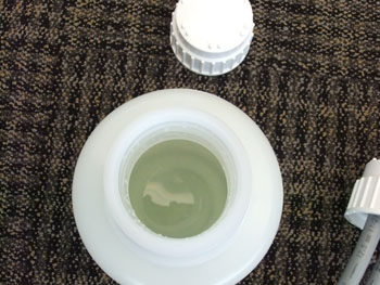
- FLUID APPEARANCE CHANGE – If there is any air in the system,
the fluid in the purge kit will become a foamy or frothy color. If
there is no air in the system, the fluid will remain a clear, or slightly
lime green color.
- FLUID LEVEL – During purging the fluid level in the bottle may rise and fall approximately 2-3cm. If the fluid level rises to the top of the bottle, turn off the gantry 120 vac and, using an appropriate container, remove enough fluid from the bottle to ensure that the bottle does not overfill.
- Once the fluid is not foamy/frothy colored AND the fluid level in the bottle has stabilized, turn off the gantry 120 VAC to remove power from the heat exchanger pump
- If using the 2011 Air Purge bottle, Replace the rubber vent cover on the top of the procedure cap
- Elevate the purge bottle so that it is higher than the hose connections.
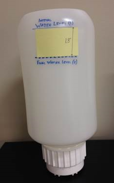
- When the fluid is clear and the level of fluid is stabilized
in the purge bottle, apply a 1.8 inch strip of paper so the top part
of the paper aligns with the fluid level in the bottle. Refer to Figure 11
Figure 11. Marking Purge Bottle fluid level
- Turn off the 120 VAC to the pump.
- Hold the purge kit up so fluid can drain from the purge kit into the accumulator. (The gantry may have to be rotated so the fluid has enough head to drain into the accumulator).
- When the fluid level in the purge bottle reaches the bottom of the 1.8 inch strip immediately disconnect the kit from the tube and heat exchanger.
- Return purge bottle to upright position on the floor.
- Disconnect the purge kit from the heat exchanger and tube.
- Reconnect the tube to the heat exchanger
- Disengage gantry rotational lock.
- Rotate the gantry such that the quick disconnects for the hose are easily accessible.
- Tighten the safety bolts on quick disconnect. The torque specification for the safety bolts is 7.9N-m (5.8 lb-ft, 70 lb-in, 81 kg-cm). NOTE: Do not severely overtighten the M6 bolts. Doing so can cause the quick disconnects to leak.
- Snug the jam nuts.
- Safely restore the system for customer use.
This will usually happen either immediately (indicating no air was present in system before purging), or after some period of time (fluid typically turns milky color then becomes clear again after approximately 10-15 minutes)
5 Finalization
Procedure
- Verify functionality of the Scanner by successfully completing a QA Phantom scan before returning it to the customer.
- Return the Air Purge Kit to your appropriate Service Tool Depot for refurbishment and/or fluid replenishment. Ensure that the kit is ready for the next engineer to order it.