- Topic ID: id_18480220
- Version: 3.0
- Date: Jan 20, 2020 8:36:17 PM
SDCB Backplane Replacement
Prerequisites
Overview
This procedure describes and illustrates the steps necessary to replace the SDCB Backplane located with the Gantry.
1 RoHS FRU notice
When Backplane is replaced from Non-RoHS to RoHS FRU, replace Power cable with provided one, because they are not compatible. System works normally with the combination of RoHS and Non-RoHS backplane.
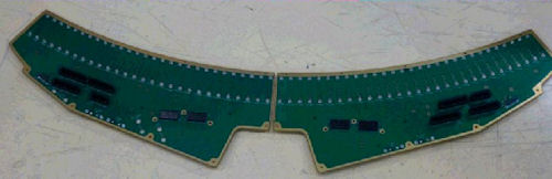
Figure 1. New Backplane
2 Gantry Preparation
Procedure
- Move table to home position, fully out and down.
- Remove gantry right side cover.
Refer to
- Stop the rotor of X-ray tube in case of Liquid Bearing Tube before HVDC off. Refer to Liquid Bearing Tube Rotor stop procedure for details.
- Turn OFF the Axial Drive and HVDC switches on the gantry’s Service Switch Panel.
- Position the detector at 12 o'clock and lock gantry rotation.
- Turn OFF the 120 VAC switch on the gantry’s Service Switch Panel.
- Remove the gantry left side cover, top covers, front and rear
covers and bore cover.
Make sure to terminate the E-stop circuit as defined in the front and rear cover removal.
3 SDCB / Detector Removal
Procedure
- Remove SDCB assembly as shown in SDCB Replacement.
- Cover the Tube Collimator port to protect it against dropped tools or screws. (Cloth or any other available item)
- Remove the Air Plenum as shown in Detector Air Plenum Removal/Installation.note:
Reminder that using the mouse right button on the above document link and selecting “Open in new Window” will keep this document open at the same time for ease in use. Can leave the Air Plenum instructions open for later use when reinstalling the plenum.
- Using the VCT Detector Replacement Procedure remove the digital detector from the gantry using sections
4.4 and 4.5.
-
There is no need to use the Replacement wizard since the detector is not being replaced.
-
Leave the detector on the hoist during backplane replacement. Swing the detector out of the way to a location that it is not a hazard during work on the backplane.
-
4 Backplane Removal
Procedure
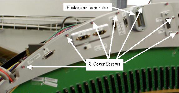
- Remove both backplane cover shields. See Figure 2.
Figure 2. Backplane Cover Shield
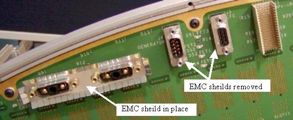
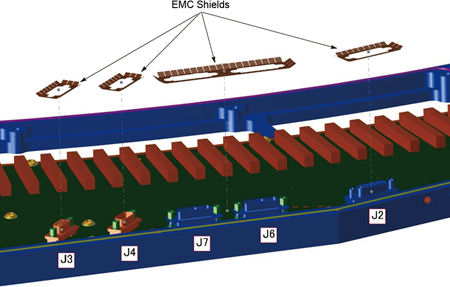
- After removing the backplane cover shields, remove the EMC connector
shields from all Sub-D connectors and set them with the backplane
cable gasket. See Figure 3for shield example.
Figure 3. EMC connector shields
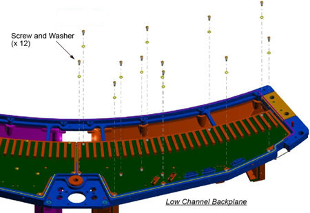
- Remove 13 screws from the high channel backplane, and remove
12 screws from the low channel backplane.
Figure 4. High Channel Backplane
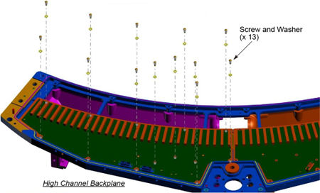
Figure 5. Low Channel Backplane
- notice
- Lift off the backplanes and place them in a static bag.
 |
5 Backplane Installation
Procedure
- Position new backplanes on the DAS plate.
- Install new 25 screws and torque to the value shown in Table 5. Do not reuse
the old screws.
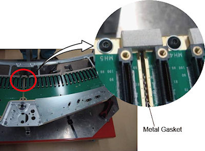
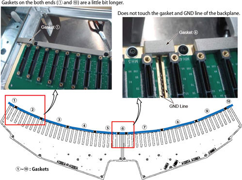
- Cut the gasket to the proper length and attach them to the backplane
as shown in illustration blow.
Figure 6. Gasket Attachment
- Place the EMC shields onto the Sub-D connectors so the fingers
are angled away from the backplane as shown in Figure 7 and Figure 8.
Figure 7. EMC Shields (High Channel Backplane)
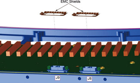
Figure 8. EMC Shields (Low Channel Backplane)
- Position the backplane cover shield and torque screws to the
value shown in Table 6. Reference Figure 2for the backplane
shield.
- Place the supplied backplane barcode sticker on the backplane shield over top of the old sticker to identify the new backplane on the system.
- Torque the backplane connector to the value shown in Table 7.
6 Detector / SDCB Installation
Procedure
- Install the Detector as shown in VCT Detector Replacement Procedure using section 4.6.
- Install the Air Plenum as shown in Detector Air Plenum Removal/Installation.
- Finish installing the DAS/Detector harnessing as shown in VCT Detector Replacement Proceduresection 4.8.
- Install the SDCB assembly as shown in SDCB Replacement.
7 Gantry Reassembly and Testing
Procedure
- Make sure the Axial Drive, HVDC and 120 VAC switches on the gantry’s Service Switch Panel are OFF.
- Install the gantry front cover, rear cover, top covers and left
side cover.
Refer to
- Enable 120 VAC HVDC and Axial Drive service switches from the service switch panel. Press the table drives enable button on the lower right corner of the service switch panel.
- From the DASTools interface run the following
rotating tests.
- Select and Run mA Ratio Test (creates/updates the bad channel map)
- Select and Run the Auto Test from DASTools.
- If all the checks pass continue with the next section. If anything fails, troubleshoot per the appropriately failed test.
- Install the gantry right side cover.
8 System Calibration
Procedure
- The detector requires up to 45 minutes to reach operating temperature prior to starting the calibration process. Failure to wait will cause artifacts later when the detector reaches operating temperature. The time to warm up starts from the time the gantry power was turned on. Check the Common Service Desktop to make sure the detector temperature is at 38 degrees C +/- 1.5 prior to starting calibrations. The operator message area will post a message when the detector is back to normal temperature.
- Perform Collimator calibration using Scanner Utilities - Collimator Cal.
- Perform Full Spectral calibration using Scanner Utilities - Detailed Cal.note:
CT# adjust is run as part of Detailed Cal, no need to run it separately.
- Perform FastCal using Daily Prep – Fastcal. (Required after every detailed calibration)
9 Finalization
Procedure
- Perform a Quality Assurance Test from the Functional Checks menu of the service manual to ensure system operation.
- Perform a Save State to save new calibration data.