- Topic ID: id_15460180
- Version: 2.0
- Date: Nov 8, 2018 1:38:16 AM
Detector Replacement Procedure
Prerequisites
Overview
Digital detector replacement.
1 System Preparation
Procedure
- At the console start the FRDM Wizard from
the Common Service Desktop Replacement tab. Figure 1 shows the main screen.
Figure 1. Process Tool
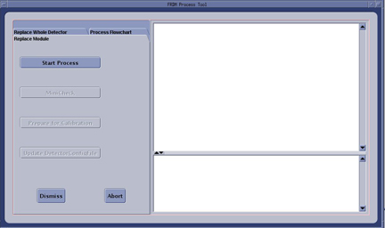
- Select the Replace Whole Detector tab and then Start Process. This will set up the system software to prepare for a Detector replacement. The physical replacement can now be performed.
- Move the table full back out of the gantry but leave it up to use as a work table.
- Stop the rotor of X-ray tube in case of Liquid Bearing Tube before HVDC off. Refer to Liquid Bearing Tube Rotor stop procedure for details.
- Remove the right side gantry cover and disable Axial Drive and HVDC from the service switch panel.
- Position the detector at 12 o'clock and lock gantry rotation.
- Shut down all gantry power from the service switch panel.
- Remove all gantry covers.
Refer to
- Cover the Tube Collimator port to protect it against dropped tools or screws. (Cloth or any other available item)
2 FRU container handling
Procedure
- Open crate and pull out the aluminum detector box. Crate handling
instructions are defined on a sheet included on the inside top cover
of the crate.note:
Foam block on ramp is attached by velcro. Pull foam block off to ease aluminum crate removal.
3 Balance Weight and Air Plenum Removal
Procedure
- Remove the gantry balance weights over top of the detector casting. Keep them in order to put them back in the exact same order when done.
- Remove the Detector Air Plenum as shown in Detector Air Plenum Removal/Installation.note:
Reminder that using the mouse right button on the above document link and selecting “Open in new Window” will keep this document open at the same time for ease in use. Can leave the Air Plenum instructions open for later use when reinstalling the plenum.
4 Digital Detector Removal
Procedure
- Disconnect cabling over the top of the digital detector and
lay the harness out of the way.
- Release cable clamps and clamp plates as necessary to release cabling from the digital detector casting but screw them back in place to keep track of them.
- All cabling and fiber optic cables will need to be loose from the detector casting.
- The routing harness goes to routing boards on either side of the detector. It is easier to disconnect them once the detector is slid forward away from the backplane.
- Loosen the cabling over the fixed block behind the balance weight threaded rods to help cable movement when installing lift hook.
- Make sure ESD strap is in use prior to continuing.
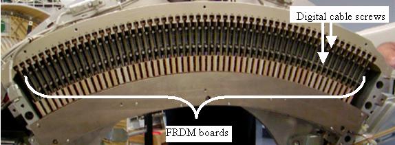
- Disconnect the Digital Modules from the backplane by disconnecting
digital screws. See Figure 2.
- Completely loosen the digital cable thumbscrews for all 57 digital cables.
- Do NOT release the wedge lock clamps. Wedge lock clamps must remain activated to keep the FRDM’s (Digital Modules) in place.
- Completely loosen both digital cable screws for a single module at the same time to avoid pulling the backplane connector at an angle. Digital cable screws should pull away from backplane freely when completely disconnected.
Figure 2. Digital Detector
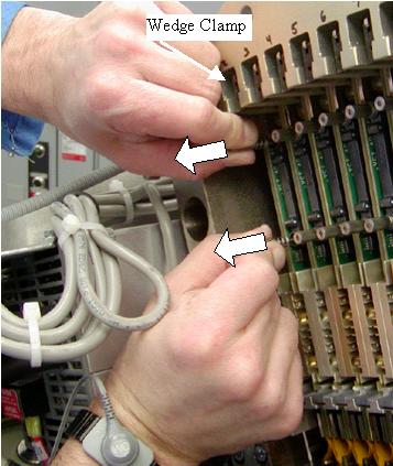
- Pull both digital screws of each module together away from backplane
(about 3.8”, 8mm) to release the digital connector from the
backplane for all 57 modules. See Figure 3.
- Module 57 allows a side view to look and confirm that the digital cable is being released from the backplane when pulling out on the digital cable screws.
- Check all digital cables again to verify that they are released.
Figure 3. Digital Module Screws
- Remove the ORP J2 connector so the cable and ferite do not catch on the detector during removal.
5 Releasing Digital Detector from DAS Plate
Procedure
- Install the gantry lift fixture with detector extension arm and the chain hoist.
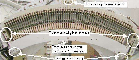
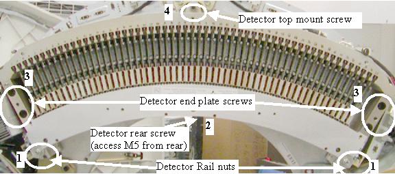
- Remove the detector top mount screw and discard only the screw,
keep the large washer (new mount screw supplied). See Figure 4.
Figure 4. Digital Detector Mount Points
- Move the top cover support out of the way.
- Use a marker to draw a line on the top cover mount joint such that it can easily be put back in place later.
- Remove the bottom screws and loosen the top screws of the top cover mount to pivot it up and out of the way.
 warning
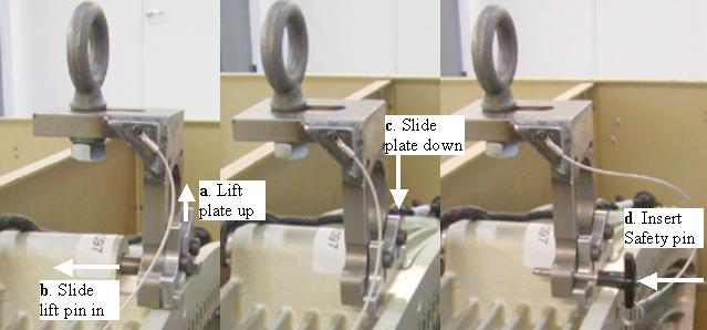
- Attach the lift hook to the Detector top mount screw hole. The
rod is inserted into the top mounting hole and the slide fits down
into the casting to lock the lift hook in place. Make sure the safety
pin is installed to keep the slide portion of the hook captive in
the detector top casting.
- Lift the slide plate up to allow the lift pin to be inserted into the detector top mount hole.
- Slide the lift pin completely into the top mount hole.
- Make sure the slide plate is down behind the front edge of the detector casting.
- Insert the safety pin into the hole on either side of the slide plate to lock the plate in the down position.
note:Figure 5 shows hook installation on detector in crate for clarity without extra components in the way. On the gantry, the balance weight failsafe rod goes through the large hole seen in the lift hook. The failsafe rod does not exist on older VCT systems.
Figure 5. VCT Detector Lift Hook
- Attach the hoist to the lift hook and take up slack on the chain.
- Remove the 4 detector end plate screws (2 on each end) and discard the screws keeping the washers.
- Remove 2 detector rail nuts and discard. New nuts are in the supplied mounting kit.
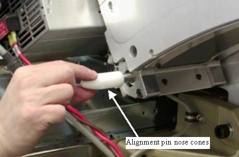
- Attach the alignment pin nose cones on each side of the detector
to protect the threaded ends of the alignment pins during removal
and installation. See Figure 6.
Figure 6. Alignment pin nose cones
- Remove the M5 hex screw (4mm hex wrench) from the rear of the gantry (keep and reuse this screw). See Figure 4.
- Slide the digital detector away from the backplane to access the routing boards on either side of the detector.
- Disconnect the black harness from both sides of the detector.
- Slowly slide the digital detector away from gantry watching
for any cable or other component obstructions. note:
Detector is sensitive to high humidity. If there is a bag included in the crate for return, refer to the instructions supplied with the crate when repackaging the detector.
- Lower the digital detector into the FRU crate and mount using the supplied bolts.
- Using the Aero-duster, clean out all backplane digital connectors to make sure no particles are in the connectors prior to installing the new detector.
6 Digital Detector Installation
Procedure
- Remove the top mount screw from the new detector in the crate
to allow installation of the lift hook.note:
The new detector comes with a cover plate installed to protect the modules during shipment. Leave this cover in place until the detector is mounted on the gantry.
- Transfer any needed cable clamps from the old detector to the new detector in the same location for ease of reference later.
- Switch the lift hook to the new detector. Attach the lift to the new digital detector.
- Lift the new detector out of the crate.
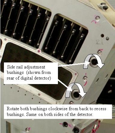
- On the back side on each end of the detector, rotate the adjustment
bushings clockwise as looking from the back of the detector to make
sure they are not sticking out prior to detector installation. See Figure 7.
Figure 7. Digital Detector Adjuster Bushings
- Rotate the top center mount screw adjustment bushing (on the DAS plate) clockwise so it is not sticking out of the plate. This bushing and the side bushings will be readjusted in an upcoming step just prior to putting the screws in.
- Carefully slide the detector onto the alignment pins. Connecting the cables to the routing boards on each side of the detector as you slide it on will make that task easier.
- Remove the nose cone alignment pin guides and install the new
detector rail nuts (with lock washers). See Figure 8 for an overview of the mounting order.note:
Use the new mounting hardware supplied with the detector as noted.
Figure 8. Digital Detector order of mounting
- Torque detector rail nuts in a 2-step process using the torque
settings shown in Table 7 and Table 8.
- Install the rear screw and torque to the values shown in Table 9.
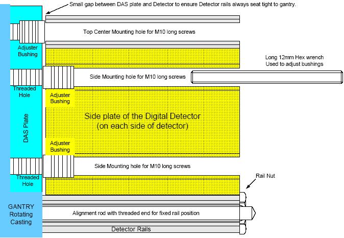
- Insert a long 12 mm hex bit (don't use a ratchet handle), supplied
with the system, into the holes for the end plate screws to access
the spacers. Turn clockwise until the spacers are tight using your
hands only, no wrench (bushing will be against the DAS plate). See Figure 9.
- The adjuster bushings are just to take up any space between the detector end plates and the DAS plate.
- Using more than hand force will cause the detector casting to bow when torquing the last screws.
Figure 9. Detector Adjuster Bushing Drawing
- Install the new detector end plate screws (2 per side) making sure the large washers are on the screws. They must have the large washer required for proper seating.
- Torque the 4 detector end plate screws first to the initial
setting and then all 4 to the final settings shown Table 10 and Table 11.
- Insert a long 12 mm hex bit (no wrench) into the top mount hole
to access the spacer. Turn counter clockwise until the spacer is tight using your hands only, no wrench (bushing
will be against the detector casting).
- This is just to take up any space between the Detector casting and the DAS plate.
- Using more than hand force will cause the detector casting to bow when torquing the screw.
- Install the new top mount screw with large washer and torque
first to the initial setting and then to the final setting shown in Table 12 and Table 13.
- Remove the protective cover from the detector by removing the 3 screws. Put the cover on the old detector in the using the same 3 screws.
- Carefully install and finger tighten both digital cable thumb
screws using the process below to help avoid cross threading. The
screws will go in easy when properly aligned.
- Pull the digital cable screws away from the backplane initially and then in toward backplane to help initial connector alignment. Use a flashlight if necessary to see if the connector is aligned to the backplane socket. A “click” can be heard when you set down the screws indicating the screws have hit the backplane threaded socket.
- Rotate the screws counter clockwise to hear a clicking sound made by the threads of the screw and threads of the socket. This will insure that the screws are lined up to the connector prior to threading them in.
- Start both screws into the sockets. Thread both screws in together so the cable edge connector is pulled into the backplane straight. Stop and back out the screws if any squeak is heard as this indicates cross threading. Try rotating the screws counter clockwise until you hear a second “click”. This can help if the screw was previously cross threaded to avoid the crossed threads.
- May need to carefully pull the digital cable screws to one side to help alignment if needed while performing steps a-c above.
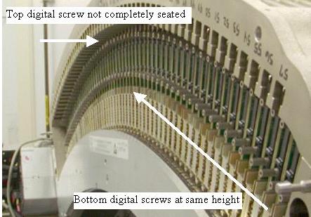
- When done seating all digital screws, look across the digital
screws from the side to see if any screws are sticking out. This
is a quick indication of a forgotten screw or potentially cross threaded
screw that needs to be backed out and reinserted
Figure 10. Detector side view
- Ensure all digital cable screws are finger tight first, then
torque to the values shown in Table 14.
7 Air Plenum Installation
Procedure
- Install the Detector Air Plenum as shown in Detector Air Plenum Removal/Installation.
- Install the gantry balance weights in the same order as removed. Torque as defined in Gantry Balance Procedure.
8 Harnessing
Procedure
- On the Low Channel side (by 48V Power Supply) route the cables
listed below together and route between studs in position as shown
in Figure 11 and Figure 12.
- 4 DAS Power and CFC/DHCB Power (5 cables)
- Generator, CFC, 2 Fiber Optic, Routing board interconnect (5 cables)
- 4 DAS Power cables
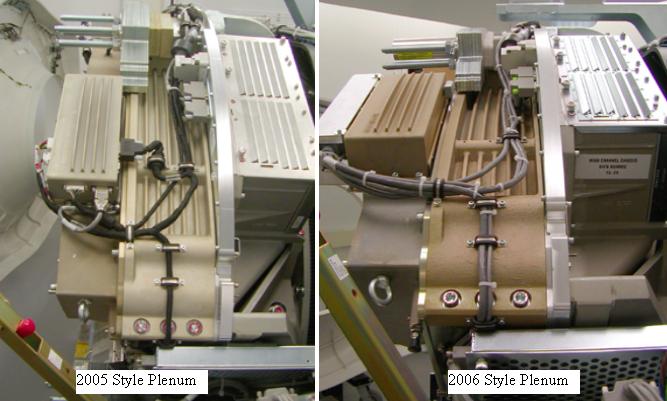
- Generator, CFC, Routing board interconnect (3 cables) (NOTE: CFC cable moves to B with 2006 style plenum)
- RCIB, CFC/DHCB Power, 2 Fiber Optic (4 cables)
note:Make sure all cable slack is pulled toward the 48V power supply and that all harnessing is secured as defined. Failure to properly strap down cabling will result in the cables hitting the stationary frame during high speed rotation.
Figure 11. Low Channel Side Cable drawing
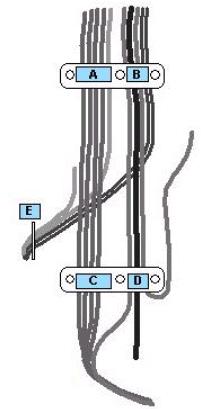
Figure 12. Low channel side cabling
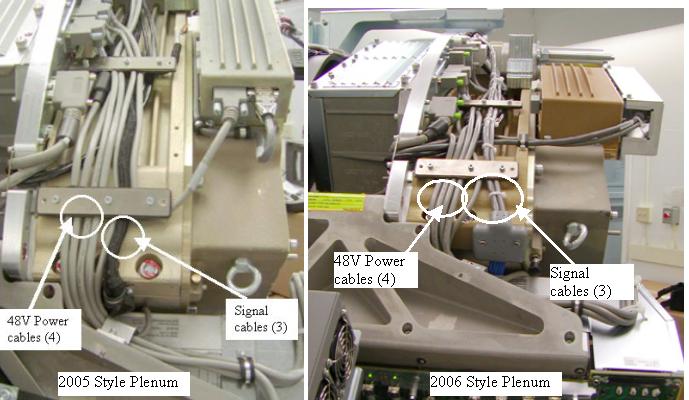
When using these instructions for detector replacement, refer to the 2006 Style Plenum (right). The 2005 Style Plenum routing is for reference when using these instructions for backplane replacement.
- On the High Channel side (ORP side) route the harness as shown
in Figure 13.
Figure 13. High Channel side cabling
- Make sure the front cover display is connected to allow the follow on testing. Don’t need to put covers on until ready for calibrations.
- Turn on the gantry 120VAC at the service switch panel.
- Release the gantry rotational lock.
- Rotate the gantry by hand looking for any potential loose cabling or connectors. Review the cable routing to make sure it is consistent with the definitions in this section.
- Enable HVDC and gantry Axial drive from the service switch panel.
9 Testing
Procedure
- From the FRDM Process Tool currently open
at the console select Minicheck and acknowledge
the pop up window if the gantry is ready to rotate.
-
The alignment check will start after the scan button is pressed when prompted. (Non-rotating scan). After 2 minutes a set of 2 plots will be shown.
-
Check the bottom plot to make sure all results are less than +/- 75. See zalignmentWizard User Instructions for more instructions if needed.
-
Since the complete detector has just been replaced, the alignment check should pass without issue. If any module is out of alignment, use the FRDM Replacement Procedure to realign the module.
-
- After exiting the alignment plot, the DASTools interface will appear. Run “mA Ratio Test” to update the bad channel map for the new detector.
- From the DASTools interface run the following
rotating tests.
- Select and Run mA Ratio Test (creates/updates the bad channel map)
- Select and Run the Auto Test from DASTools.
- If all the checks pass continue with the next section. If anything fails, troubleshoot per the appropriately failed test.
- Perform any desired quick checks if problem was not a digital issue that was already verified by the mini check tests.
- Perform a tube alignment check per the “Z align” instructions. Adjust the tube if necessary.
- Perform a tube iso alignment check per the “Iso Alignment Procedure”. Adjust the tube if necessary.
- Perform a gantry balance check and rebalance if needed.
10 Gantry Reassembly
Procedure
- Install all gantry covers remembering to enable Axial Drive
just before installing gantry right side cover. Gantry covers MUST
be in place prior to running calibrations.
Refer to
11 System Calibration
Procedure
- The detector requires up to 45 minutes to reach operating temperature prior to starting the calibration process. The time to warm up starts from the time the gantry power was turned on. The user message log will indicate when the detector temperature has returned to normal.
- From the FRDM Process Tool currently open at the console select Prep for Calibrations. The Scanner Utilities window will open.
- Perform Collimator calibration using Scanner Utilities - Collimator Cal.
- Perform Full Detailed calibration using Scanner Utilities - Detailed Cal.note:
CT# adjust is run as part of Detailed Cal, no need to run it separately.
- Perform FastCal using Daily Prep – Fastcal. (Required after every detailed calibration)
12 Finalization
Procedure
- Perform the Quality Assurance Test.
- From the FRDM Process Tool currently open at the console select Update Detector Configuration when the system is ready for customer operation. This will read and update the new detector configuration and perform any background cleanup of temporary software files created by the tool during the replacement process.
- Perform a Save State to save the new calibrations.
-
Tools Return Policy: Re-package all provided
service tools, in the original packages, and place into the FRU shipping
container. Failure to return these items will result in your Service
Contract being billed the significant cost of these tools.
-
Detector lift hook
-
Nylon thread protectors (white nose cones)
-