- Topic ID: id_18480219
- Version: 3.0
- Date: Jan 20, 2020 8:32:44 PM
SDCB DAS FRU Replacement
Prerequisites
Overview
This procedure describes and illustrates the steps necessary to replace the following parts in SDCB DAS.
-
SDCB Board Assembly
-
SDCB Power Module Assembly (Low/High)
-
SDCB Cable Assembly (Low/High)
1 Replacement Flowchart
Figure 1. Replacement Flowchart
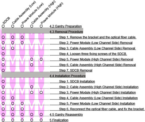
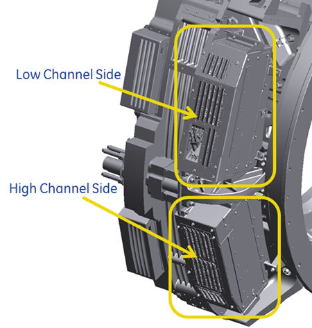
Figure 2. SDCB DAS
2 Gantry Preparation
Procedure
- Move table to home position, fully out.
- Remove gantry right side cover.
Refer to Replacement → Gantry → Enclosure → (Cover Removal Procedures).
- Stop the rotor of X-ray tube in case of Liquid Bearing Tube before HVDC off. Refer to Liquid Bearing Tube Rotor stop procedure for details.
- Turn OFF the Axial Drive and HVDC switches on the gantry’s Service Switch Panel.
- Position the detector at 3 o'clock and lock gantry rotation.
- Turn OFF the 120 VAC switch on the gantry’s Service Switch Panel.
- Remove the gantry left side cover and top covers.
- Remove the cable from the rear switch panel (if needed), and slide the rear cover backward.
- Loosen the lock screw of the right top fan of the gantry, and rotate the right top fan.
3 Removal Procedure
Procedure
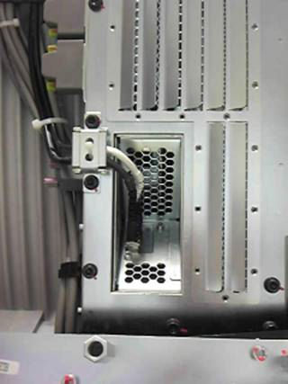
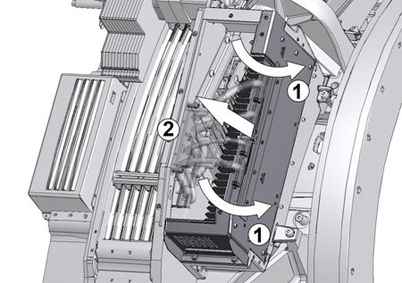
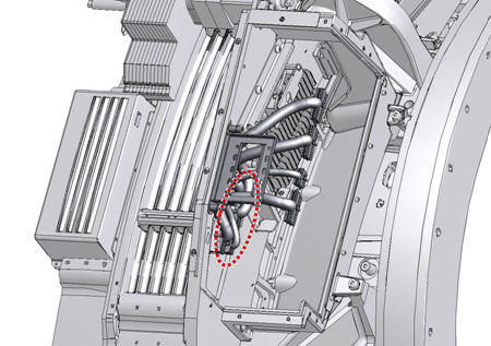
- Remove the bracket of the optical fiber cable, and disconnect
the cable from SDCB.
Figure 3. Optical Fiber Cable
-
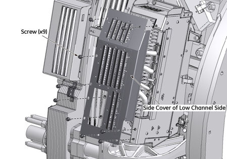
Power Module (Low Channel Side) Removal :
- Remove nine screws, and remove the side cover of the low channel side.
Figure 4. Side Cover of Low Channel Side

- notice
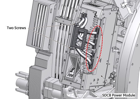
- Disconnect cable connectors form the power module, and unscrew
two captive screws.
Figure 5. Cable Assembly of Low Channel Side
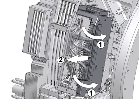
- Remove two screws and remove the power module of the low channel
side.
Figure 6. Power Module of Low Channel Side
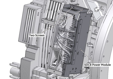
Figure 7. Power Module Removal
- Remove nine screws, and remove the side cover of the low channel side.
-
Cable Assembly (Low Channel Side) Removal :
- notice
- notice
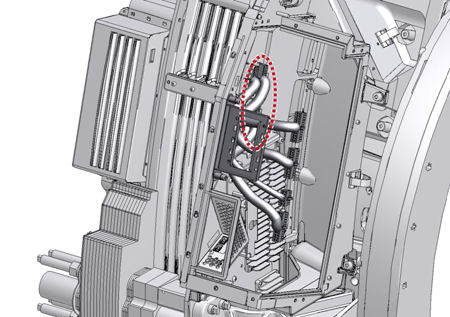
- Disconnect cable connectors (J20 ~ J23) from the low backplane.
Figure 8. Cable Assembly Removal (Low Channel Side)
- Remove the cable assembly from the gantry.
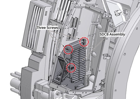
- Loosen three fixing screws of the SDCB at the low channel side.
Figure 9. Three Screws of SDCB (Low Channel Side)
-
Power Module (High Channel Side) Removal :
- notice
- Rotate the gantry until the high channel side is accessible, and lock gantry rotation.
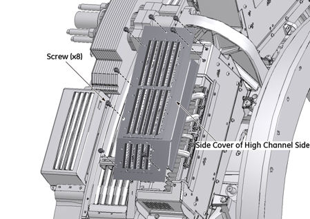
- Remove eight screws, and remove the side cover of the high channel
side.
Figure 10. Side Cover of High Channel Side
- notice
- Disconnect cable connectors from the power module, and unscrew
two captive screws.
Figure 11. Cable Assembly of High Channel Side
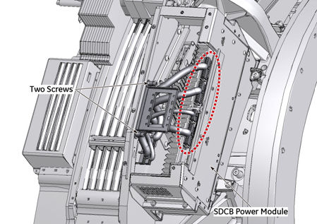
- Remove two screws and remove the power module of the high channel
side.
Figure 12. Power Module of High Channel Side
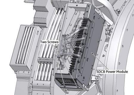
Figure 13. Power Module Removal
-
Cable Assembly (High Channel Side) Removal :
- notice
- notice
- Disconnect cable connectors (J24 ~ J27) from the high backplane.
Figure 14. Cable Assembly Removal (High Channel Side)
- Remove the cable assembly from the gantry.
-
SDCB Removal :
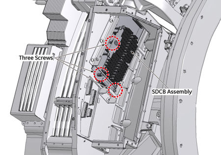
- Loosen three fixing screws of the SDCB at the high channel side.
Figure 15. Three screws of SDCB (High Channel Side)
- notice
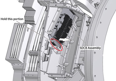
- Hold the edge of SDCB, and pull the SDCB backward slightly,
then disconnect it from the high backplane.
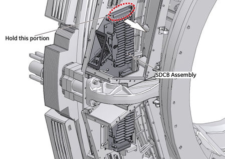
Figure 16. Disconnect SDCB (High Channel Side)
- Rotate the gantry until the low channel side is accessible, and lock gantry rotation.
- Hold the edge of SDCB, and pull the SDCB backward slightly,
and disconnect it from the low backplane.
Figure 17. Disconnect SDCB (Low Channel Side)
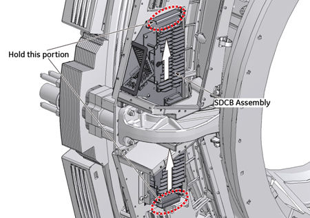
- Hold the edge of SDCB, and carefully drag up the SDCB from the
gantry.
Figure 18. SDCB Assembly Removal
- Loosen three fixing screws of the SDCB at the high channel side.
4 Installation Procedure
|
|
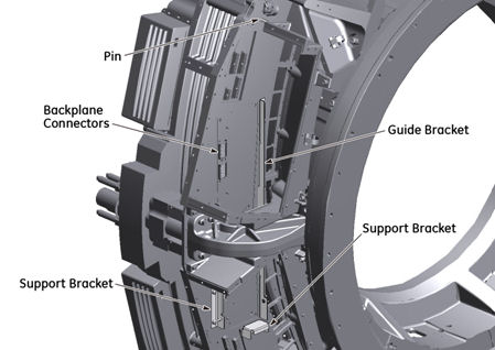
Figure 19. Guide Bracket and Support Brackets
Procedure
-
SDCB Installation :
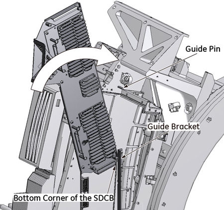
- Attach the bottom corner of the new SDCB to the guide bracket.
Figure 20. Guide bracket and New SDCB
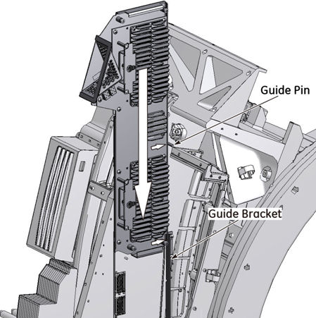
- Hold the side of SDCB against the guide pin, and slide the SDCB
down along the guide bracket carefully, then set the SDCB in the support
bracket.
Figure 21. SDCB Installation
- notice
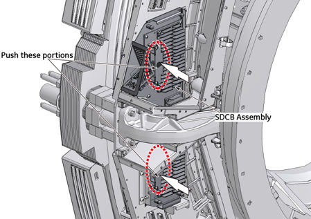
- Push the SDCB forward slightly, and connect it to the backplane.
Figure 22. SDCB Connection
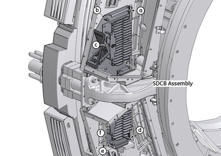
- Tighten the six captive screws of the SDCB to fix it to the
backplane as follows:
-
High channel side three screws (d, e and f) temporal fix.
-
Low channel side three screws (a, b and c) temporal fix.
-
Tighten the low channel screw on handle (c) with torque 7.9Nm.
-
Tighten the low channel side remaining two screws ( a and b ) with torque 7.9Nm.
-
Tighten the high channel screw on handle (f) with torque 7.9Nm.
-
Tighten the high channel side remaining two screws (d and e) with torque 7.9Nm.
-
Figure 23. Six Captive Screws of the SDCB
- notice
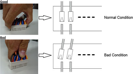
note:When power cable is reconnected, hold the connector housing and insert the connector parallel to the board to prevent any damages to the circuit board (especially backplane).
- Attach the bottom corner of the new SDCB to the guide bracket.
-
Cable Assembly (High Channel Side) Installation :
Connect the cable assembly (J24 ~ J27) to the backplane at the high channel side (see Figure 14).
-
Power Module (High Channel Side) Installation :
- Install the power module of the high channel side, and tighten the two screws temporarily (see Figure 12).
- Tighten the two screws, and reconnect the cable assembly to the power module of the high channel side (see Figure 11).
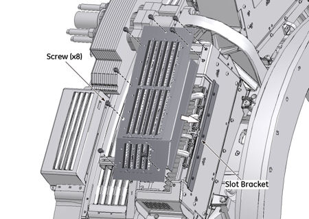
- Reinstall the side cover of the high channel side (Make sure
that the side cover is properly inserted into the slot bracket of
the power module), and tighten the two screws of the power module
and eight screws of the side cover.
Figure 24. Slot Bracket (High Channel Side)
- notice
note:When power cable is connected, hold the connector housing and insert the connector parallel to the board to prevent any damages to the circuit board (especially backplane).
-
Cable Assembly (Low Channel Side) Installation :
Connect the cable assembly (J20 ~ J23) to the backplane at the low channel side (see Figure 8).
-
Power Module (Low Channel Side) Installation :
- Install the power module of the low channel side, and tighten the two screws temporarily (see Figure 6),
- Tighten the two screws, and reconnect the cable assembly to the power module of the low channel side (see Figure 5).
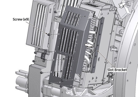
- Reinstall the side cover of the low channel side (Make sure
that the side cover is properly inserted into the slot bracket of
the power module), and tighten the two screws of the power module
and nine screws of the side cover.
Figure 25. Slot Bracket (Low Channel Side)
- Reconnect the optical fiber cable, and fix the bracket.
5 Gantry Reassembly
Procedure
- Make sure the Axial Drive, HVDC and 120 VAC switches on the gantry’s Service Switch Panel are OFF.
- Re-place the right top fan of the gantry.
- Reinstall the gantry front cover, rear cover, top covers and
left side cover.
Refer to
- Turn on the 120 VAC, HVDC and Axial drive service switches.
- Reinstall gantry right side cover.
6 Finalization
Procedure
- Perform a [Quality Assurance Test] from the [Functional Checks] menu of the service manual to ensure system operation.