- Topic ID: task_xnx_rqv_rgb
- Version: 2.0
- Date: May 22, 2020 4:03:31 AM
Rotating 48V Power Supply Replacement
Prerequisites
Overview
This procedure defines the steps necessary to replace the 1.8kW 48V power supply (5797615) and the 1.8kW 48VDC power supply (5351847-x) to the new 1.8kW 48VDC power supply (5797614).1 Power Supply Assembly Removal
Procedure
- Remove gantry side covers and disable Axial drive and HVDC from the Service Switch Panel.
Refer to
- Rotate the gantry to position the 48V power supply on the right side of the gantry above the service switch panel and lock gantry in position with rotational lock.
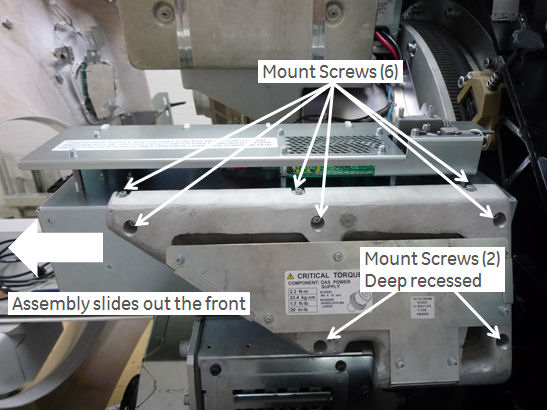
Figure 1. 48V Power Supply Assembly (5797615)
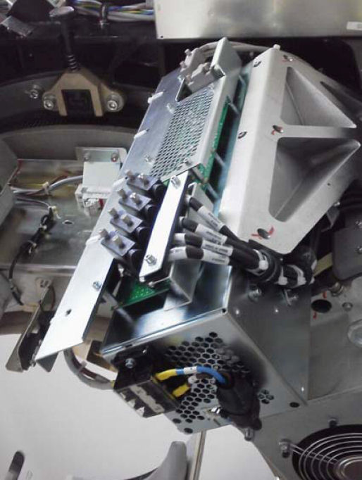
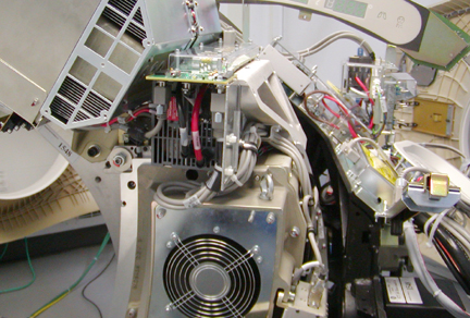
Figure 2. 48V Power Supply Assembly (5351847-x)
- Stop the rotor of X-ray tube in case of Liquid Bearing Tube before HVDC off. Refer to Liquid Bearing Tube Rotor stop procedure for details.
 danger
- Turn off the gantry 120 VAC switch on the service panel. Power down the console and use LOTO procedures to make sure gantry power is removed.
- Remove the gantry top covers and front cover.
Refer to
- Disconnect the AC input cables from the terminal strip on the front of the power supply.
- Remove the 8 mounting screws attaching the power supply assembly to the cast frame and slide the supply out the front of the gantry.
1.1 For 5797615 Power Supply Assembly Removal
Procedure
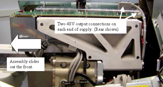
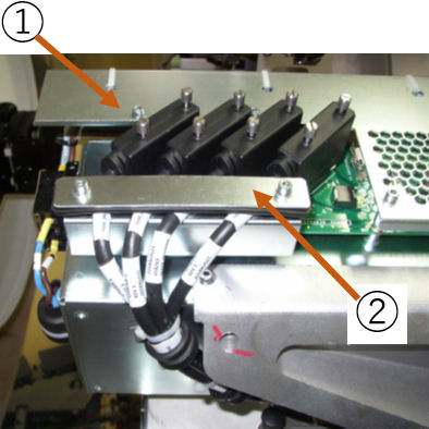
- Remove the Power supply output connectors on the rear of the supply as shown in Figure 3.
Figure 3. 48V Power Supply Output Connectors
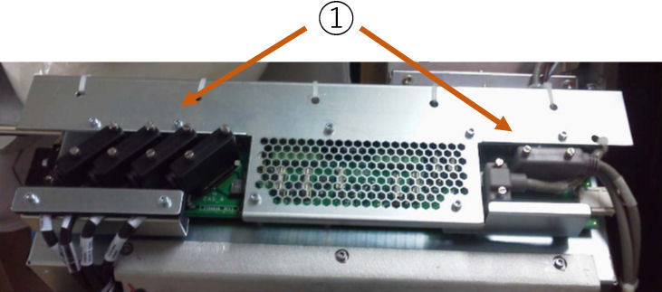
➀ DC Output Connectors - Disconnect the AC input cables from the terminal strip on the front of the power supply. Make note of any other tywraps removed during supply removal for reinstallation later.
Figure 4. AC Input Cable
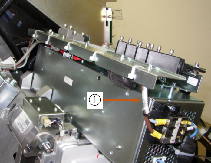
➀ AC Input Cable - Remove the 8 mounting screws attaching the power supply assembly to the cast frame and slide the supply out the front of the gantry.
Figure 5. Power Supply Removal
1.2 For 5351847-x Power Supply Assembly Removal
Procedure
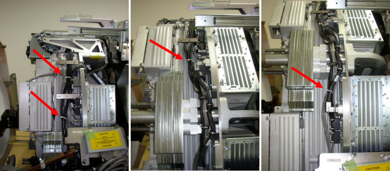
- Remove the Power supply output cables on the front and rear of the supply as shown in Illustration 2 and Illustration 3. Ty wraps for the front cable support need to be removed as shown. Make note of any other ty wraps removed during supply removal for reinstallation later. Also remove cable clamps attaching the output cables to the power supply assembly.
Figure 6. Example 48V Power Supply Front View
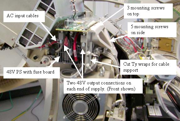
Figure 7. Example 48V Power Supply Side View
- Disconnect the AC input cables from the terminal strip on the front of the power supply.
- Remove the 8 mounting screws attaching the power supply assembly to the cast frame and slide the supply out the front of the gantry.
2 Power Supply to DAS Cable Replacement
Procedure
- Remove the existing 48V Power Supply J2 to DAS Backplane J6,J7,J8,J9 Cable (P/N 5129366).
- Route the new DAS cable (P/N 5798535) between 48V Power Supply J2A,J2B,J2C,J2D to DAS backplane J6,J7,J8,J9 connector.
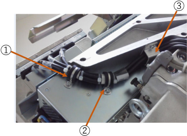
Figure 8. Cable Routing
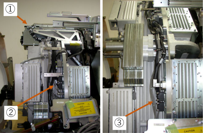
➀ Cable Connector J2A,J2B,J2C,J2D ➁ Cable Connector J6,J7 ➂ Cable Connector J8,J9 - Fix the DAS cable at clamp position. Clamp(A) and (B) are separately packed in package.
Figure 9. Cable Fixing Plate
➀ Cable Connector J2A,J2B,J2C,J2D ➁ Cable Fixing Plate Figure 10. Cable Clamp
➀ Cable Clamp (A) ➁ Cable Clamp (B) ➂ Cable Clamp - Band the cable by Ty-wrap if there is loose condition on the way of routing.
Figure 11. Cable Binding
- Torque the D-sub connector screws to the following value.
0.22 N-m 0.16 lb-ft 1.95 lb-in 2.24 Kg-cm
important:
3 Power Supply Assembly Installation
Procedure
- Slide the new power supply assembly in from the front of the gantry.
- Install the 8 - M4 screws to attach the supply to the cast frame.
- warning
- Torque the 6 - M4 screws near the fuse board to the following value:
- The 2 deep recessed screws are hard to get to if you do not have a 3 inch long 3 mm driver bit. Either of the following 2 steps can be used to tighten these 2 screws.
- Preferred method: Using a 3 mm (3 inch long) driver bit, torque the 2 deep recessed screws to:
- Alternate Method: Using a 3 mm hex wrench seat the screws then continue to turn 1/4 turn to apply sufficient torque. Do not over tighten. Use the approximate force applied to torque the other 6 screws as a guide to the force limit for these 2 screws. If either screw strips out the threads of the power supply you will need to order a new supply. Do not allow operation of the system with stripped mounting screws.note:
Do NOT use this alternate torque method anywhere else in the system unless specifically defined by the service procedure.
- Preferred method: Using a 3 mm (3 inch long) driver bit, torque the 2 deep recessed screws to:
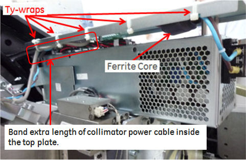
- Reconnect input and output cabling to power supply assembly as removed. Install Ty-wraps in all locations removed during supply removal.
- Torque the D-Sub connector screws to the following value.
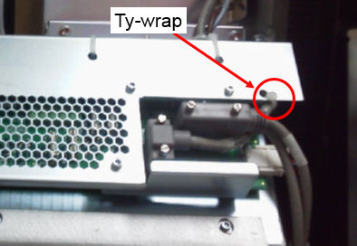
Figure 12. Ty-wraps Installation
- Torque the 120V input power connections (2 screws) to the following value:
- Restore power to the system and gantry per LOTO procedures.
4 Finalization
Procedure
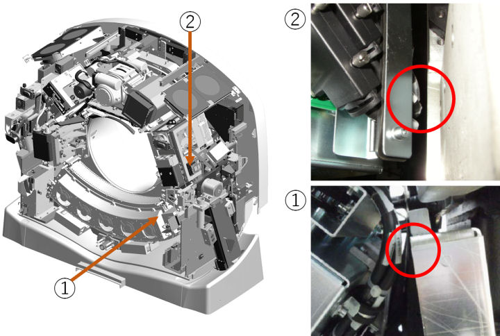
- Confirm that there is clearance between DAS cable and Gantry.
Figure 13. Clearance Check
- Check power supply output levels per 48 Volt Power Supply Checks.
- Perform a Gantry Rotation Safety Check.
- Check Gantry Balance to verify gantry is still balanced.
- Run DASToolsAuto Test to verify that no noise is introduced by the new supply.
- Turn OFF the Axial Drive, HVDC and 120 VAC switches on the gantry’s Service Switch Panel.
- Install the gantry front, top and left side covers.
Refer to
- Enable 120 VAC HVDC and Axial Drive service switches from the service switch panel. Press the table drives enable button on the lower right corner of the service switch panel.
- Install the gantry right side cover.