- Topic ID: id_18480399
- Version: 7.0
- Date: Jan 23, 2022 10:53:14 PM
Planned Maintenance Schedule W
1 Schedule W Overview
This P.M. is applied to system within warranty period (one year after installation). The recommended timing is 7 ~ 9 months after installation or 1.3 million gantry revolutions, whichever comes first.
This schedule includes a general cleaning and inspection of the Gantry, Console and Table. In addition, you will inspect any Options installed at the customer site. The tools, test equipment, and consumables listed here are needed to complete Schedule W
Every site must maintain a site log. It can be a GE Site Log, or a notebook or binder that you create. A System Service History also is available through iCenter or ISD tools.
During the course of the PM, if you find anything that you determine is critical to quality or to the operation of the system, then you should record it on the PM Report Form, and schedule additional time for specific corrective action.
You will need to open the PM Report form that corresponds to this PM Schedule (The form is located on SIMS Content Viewer). Fill in the Report form as you complete the PM Schedule. Print one copy for your Site Log. You may need to print a second copy for the customer, if requested.
2 Personnel and Time Requirements
3 Tools and Test Equipment
4 Consumables
5 Preliminary Requirements
You may do any of the following remotely, if possible.
6 E-Stop and Patient Tilt sensor Inspection
6.1 Test E-stops
Complete the 2 Verify Display Lights and E-Stop Buttons in the General Gantry Inspection.
6.2 Emergency Off Switch (On wall)
If your system has an Emergency OFF switch on the wall, verify that the Emergency Off switch is working properly.
6.3 Test Patient Tilt Sensor
Complete the 3 Test Patient Tilt Sensors in the General Gantry Inspection.
7 General Console Cleaning & Inspection
7.1 Clean Component Filters, Fans & Grills
Complete the 1 General Console Cleaning and Inspection in General Console Cleaning and Inspection procedure.
7.2 Seismic Anchor Check (if necessary)
Complete the 3 Seismic Anchor Inspection in General Console Cleaning and Inspection procedure.
8 Slip ring & Brush Block Inspection and Maintenance
8.1 Remove Slip Ring Brush Debris
Remove Slip Ring Brush Debris. (For procedures, see Inspect Brush Block and Brushes and Remove Slip Ring Brush Debris.)
8.2 Slip Ring Tracks Inspected
Inspect the Slip Ring Tracks. (For procedures, see Inspect Brush Block and Brushes and Remove Slip Ring Brush Debris.)
8.3 Clean Brush Blocks
Inspect the Brush Blocks. (For procedures, see Inspect Brush Block and Brushes and Remove Slip Ring Brush Debris.)
8.4 Brush Tip Inspection
Inspect the Brush Tips. (For procedures, see Inspect Brush Block and Brushes and Remove Slip Ring Brush Debris.)
9 Gantry Filter Cleaning
9.1 Clean Gantry Heater Filter
Complete 4 Gantry Filter Cleaning, in Gantry Filter Cleaning and Rotational Checks procedure.
9.2 Rotating Path components & Cables Inspection
Complete 6 Rotating Path Components and Cables Inspection in Gantry Filter Cleaning and Rotational Checks procedure.
10 Tube Heat Exchanger & Jedi Fan Inspection
10.1 Inspect/Clean Tube Heat Exchanger
Complete a Tube Heat Exchanger inspection. (For procedures, see Clean Tube Heat Exchanger and Clean JEDI Inverter Fans.)
10.2 Inspect/Clean JEDI Inverter Fan
Complete a JEDI Inverter Fan inspection. (For procedures, see Clean Tube Heat Exchanger and Clean JEDI Inverter Fans.)
11 General Table Cleaning & Inspection
11.1 Inspect/Clean Table Pan
-
Move the table to ISO elevation and the cradle to the maximum OUT position.
-
Turn the power OFF (120 VAC, Axial Drive and HVDC) at the gantry service switch panel.
-
Complete 1 Preliminary Tasks in General Table PM.
11.2 Inspect Table Covers
Complete 10 Inspect Table Covers in General Table PM.
11.3 Inspect Cradle Accessory Attachment (Note in Comments if anything is replaced)
Complete 11 Cradle Accessory Attachment Inspection in General Table PM.
11.4 Check Tape Switches
-
Restore the power OFF (120 VAC, Axial Drive and HVDC) at the gantry service switch panel.
-
Complete 12 Tape Switches Inspection in General Table PM.
12 NGPDU
Complete 2 Seismic Anchor Bolt Checks in NGPDU Checks procedure.
13 System Options
If your site has the following options, complete an inspection of each. (For procedures, see Options Inspection.)
- Nemote Injector option
- RCK-AVIMOS option
14 Gantry Verifications (if required)
-
Turn OFF the Axial and HV switches at the gantry service switch panel.
-
Complete the following Gantry Verification procedures:
-
Turn ON the Axial and HV switches at the gantry service switch panel.
-
Complete the HHS Scans. (For procedures, see HHS Scans.)
15 Quality Assurance Test
15.1 Scan Window Inspection/Replacement
-
Turn the 120 VAC, HV and Axial power OFF at the gantry service switch panel. (For procedures, see Safety-Equipment Service-Gantry)
-
Reinstall front, rear, and top covers to the gantry.
-
Install and inspect the Scan Window. (For installation procedures, see Replacement-Gantry Enclosure-Gantry Scan Window Removal and Re-install.)
-
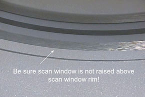
Inspect the scan window for physical damage.
-
Check that the scan window is not raised higher than the front or rear cover at any location on the circle, and that the window is not wrinkled (see Figure 1).
Figure 1. Scan Window
-
Replace the scan window if it is damaged. (If you need to replace the scan window, follow the procedures in Replacement-Gantry Enclosure-Gantry Scan Window Removal and Re-install to remove the old window and install a new one.)
-
-
Turn the 120 VAC power ON at the gantry service switch panel. (For procedures, see Safety-Equipment Service-Gantry.)
-
Rotate the gantry by hand and inspect rotational clearances.
-
Power up the system (for procedures, see Section 2.2 of Equipment Service - Lockout-Tagout-PPE).
-
Turn on the Axial Enable and HVDC switches at the gantry service switch panel. (For procedures, see Safety-Equipment Service-Gantry)
-
Install the gantry side covers.
15.2 QA Phantom Inspection
Verify there is no crack and no damage on QA phantom.
15.3 Quality Assurance Test
Complete the Quality Assurance Test. (For procedures, see Quality Assurance Test)
15.4 X-ray on indicators
Complete the System Scanning Test. (For procedures, see System Scanning Test.) While completing the test, do the following verifications.
-
Verify that the following X-ray On indicators light up:
-
SCIM
-
Gantry Front
-
Gantry Rear (To avoid walking into the room during a scan, you may want to use a mirror to check this X-ray indicator.)
-
Room Warning Light
-
-
Verify that the following scan control push-button are operational:
-
Start scan (and keypad lights).
-
Stop scan (and keypad lights).
-
Pause scan.
-
Advance to scan.
-
Stop table.
-
16 Finishing Up
16.1 Confirm Save State Completed
-
Start Save System State (For procedures, see Section 4.1 in System State Save Restore.)
-
Confirm Save System State completed successfully.
16.2 PM Paper work completed for this site
-
Update the site logs. (For procedures, see Update Site Logs.)
-
Complete all required PM paperwork.