- Topic ID: id_16157504
- Version: 5.0
- Date: Aug 10, 2021 9:57:52 PM
Power Unit Replacement
Prerequisites
Overview
Procedure summary:
-
If possible, upload JEDI database (from JEDI to console)
-
Remove power unit mounting screws
-
Replace power unit
-
Reattach wiring
-
Reload JEDI software and appropriate database
1 Power Unit Removal
Procedure
 danger
- Upload JEDI database (from JEDI) if you wish to retain the existing database after new Power Unit installation. In most cases you will want to perform this step, however it may not be possible, depending on the failed KV control board. If it’s not possible, move on.
- Move table to its lowest elevation.
- Remove, and set aside, both gantry side covers, top covers, front cover.
- Stop the rotor of X-ray tube in case of Liquid Bearing Tube before HVDC off. Refer to Liquid Bearing Tube Rotor stop procedure for details.
- Turn OFF all 3 switches (Axial Drive, HVDC, 120VAC) on the STC backplane.
- Remove power at main disconnect (A1) panel. Use proper Lockout/Tagout procedures.
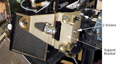
- Remove the two M12 screws from the right front gantry cover
mounting bracket, remove and set aside the bracket.
Figure 1. Support Bracket Removal
- Rotate the Gantry until the power unit reaches the 3 o’clock position.
- Engage gantry rotational lock.
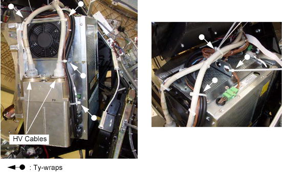
- Cut any tie-wraps holding the cables to the power unit.
- Use the spanner wrench to remove the high voltage cable connector
from the tank on the power unit.
-
Ground the ends of the H.V. cable to the Gantry frame, to endure no voltage exists at the end of the cable.
-
Use rags or paper towels to wipe excess oil from the H.V. Cable Connector and tank well.
-
Stuff the tank wells with paper towels to absorb any oil.
Figure 2. HV Cable Configuration
-
- Disconnect the following cable connectors:
-
Fan Power Cable Connector
-
CT I/F J3 Connector (<-> ORP)
-
J5 Connector (<-> DAS)
-
J6 Connector (<-> Auxiliary Assy)
-
J7 Connector (<-> Power I/F)
-
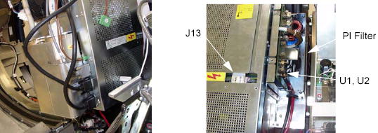
PI Filter J1 (<-> Auxiliary Assy, HEMIT Tank)
-
U1, U2 (<-> Slip Ring)
-
KV Cont J3 (<-> Auxiliary Assy)
-
J14 (<-> Auxiliary Assy)
Figure 3. Cable Connections
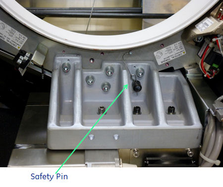
 In case of Cj M40, safety pin needs to be removed, refer to the picture below.
Figure 4. Safety Pin
-
- Remove the power unit from the gantry:
- warning
- Attach the hoist to the boom arm in the gantry.
- Attach the hoist lifting chain to the lifting bracket on the power unit top.
- Remove slack from the hoist chain.
- Remove the four M12 screws and one 19 mm nut that fasten the
power unit to the rotating base.
In case of Cj M40, remove five M12 screws.
- Use the hoist to lower the power unit to the floor.

2 Power Unit Installation
Procedure
- Ensure that Lockout/Tagout procedure has been applied, and that gantry power is removed.
- Ensure that gantry rotational lock is engaged and gantry does not rotate by attempting to rotate gantry by hand.
- Using the hoist, attach new power unit to gantry.
- Insert the safety pin, refer to Figure 4.
- Torque the four M12 screws and one 19 mm nut to the following
pre-load value.
In case of Cj M40, torque five M12 screws.
- Torque the four M12 screws and one 19 mm nut to the following
final value.
- Replace the control module covers (part1 and part2) of the new power unit with the existing one.
- Re-connect all the cables.note: Follow the following procedure for tightening HV cable ring nuts.
- Lightly wet the new rubber quad ring with transformer oil.
- Return the quad ring to its slot at the top of the receptacle retaining ring.
- Pour transformer oil into the receptacle approximately 13 ml (reference only, please adjust the oil amount as necessary).note: DO NOT use the syringe in vertical position, this will result in air bubbles which increase the chances of the high voltage breakdown.
Figure 5. Filling Receptacle

- Align the cable terminal orienting key with the notch in the receptacle.
- Slowly insert the cable, to engage the connector pins, and seat the cable in the receptacle.note:
After installing the cable to the receptacle, confirm the transformer oil is spilled over a little from the receptacle as shown in Figure 6.
If the transformer oil is inappropriate amount, adjust the oil amount as necessary.
Figure 6. Appropriate Amount of Transformer Oil
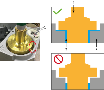
1 HV Cable 2 Transformer Oil 3 Receptacle - Tighten the cable ring nut by ¼ to ½ of a full turn by spanner wrench after the gap is closed and friction is felt by hand.
- Carefully wipe up all excess oil.
3 Finalization
Procedure
- Perform Gantry Rotation Safety Check.
- Perform Gantry Balance Procedure.
- Perform Flash Download.
- Perform Restore Runtime Parameters (Generator Tool).
- Perform Meter Verification.
- Perform HV Tank Feedback Resistor Verification.
- Perform Filament Calibration (Generator Tool).
- Perform HHS Scans.
- Perform System Scanning Test .
- Perform Quality Assurance Test.