- Topic ID: id_16157539
- Version: 4.0
- Date: May 24, 2022 2:04:56 AM
Planned Maintenance Schedule C
1 Schedule C Overview
Complete Schedule C one third of every year. This schedule includes a general cleaning and inspection of the Gantry and Console. The tools, test equipment, and consumables listed here are needed to complete Schedule C.
Every site must maintain a site log. It can be a GE Site Log, or a notebook or binder that you create. A System Service History also is available through iCenter or ISD tools.
When reviewing the error logs, or during the course of the PM, if you find anything that you determine is critical to quality or to the operation of the system, then you should record it on the PM Report Form, and schedule additional time for specific corrective action.
You will need to open the PM Report e-form that corresponds to this PM Schedule. (The e-form is located on SIMS Content Viewer) Fill in the Report form as you complete the PM Schedule. Print one copy for your Site Log. You may need to print a second copy for the customer, if requested.
2 Personnel and Time Requirements
3 Tools and Test Equipment
4 Consumables
5 Preliminary Requirements
You may do any of the following remotely, if possible.
-
Before beginning this PM Schedule, verify that the last PM Schedule completed was Schedule B.
-
Determine if any PM tasks were completed earlier as part of a service action.
note: If you changed a tube within the last 12 months, you do not need to do the following PM procedures:-
Gantry Verification (including HV Tank Feedback Resistor Verification and Meter Verification).
-
HHS Scans
-
6 Initial Procedures
-
Check the Temperature and Humidity in the scan room; record these on the PM Report Form. (Use the temperature and humidity tool [Oregon Scientific BAR608HGA], or an equivalent tool.)
-
Remove the gantry right side cover. (For procedures see
-
Complete the General Gantry Inspection, including the following: (For procedures, see General Gantry Inspection.)
-
Test Display Lights and E-stop Buttons
-
Test Patient Tilt Sensors
note: Ignore inspection of the Listen for Unusual Noises. -
7 RCK-AVIMOS Inspection
As a monitoring system, the inspection is necessary to ensure accuracy and clarity of the AVIMOS. (For procedure, see RCK Planned Maintenance)
8 Phantom Inspection
Verify there is no crack or damage on QA phantom.
9 Power Off, Gantry Covers Off
-
Move the table to lowest position.
-
Move the gantry to zero degrees.
-
Power down the system and apply LOTO (for procedures, see Equipment Service - Lockout-Tagout-PPE).
note: If your system has an Emergency OFF switch on the wall, use it rather than the A1 Off switch to verify that the Emergency Off switch is working properly. -
If installed, confirm that the UPS power is disconnected when the Emergency Off device is pushed.
-
Remove side, top, front, and rear gantry covers. (For procedures see,
9.1 Console
Complete the General Console Cleaning and Inspection. (For procedures, see General Console Cleaning and Inspection.)
9.2 Gantry
-
Inspect the Brush Block, Brushes, and Remove Slip Ring Brush Debris. (For procedures, see Inspect Brush Block and Brushes and Remove Slip Ring Brush Debris.)
-
Complete a Gantry Filter Cleaning and Rotational Checks, including the following: (For procedure, see Gantry Filter Cleaning and Rotational Checks)
-
Clean DAS Detector Plenum Filter
- Clean Gantry Heater Filter
-
Clean DAS DIFB Fan Filters (only for PDAS)
-
Clean top cover fans
-
Clean Detector Face Plate
-
Rotating Path Components and Cables Inspection
-
For GDS, see CTPM-1322 (Clean DAS, DUCT Fan Filters)
For PDAS, see Clean Pancake DAS Fan Filters
10 HV Cable Candle Stick Inspection
Remove candle sticks which are connected to Tube, HV Tank, and HEMIT Tank, and perform visual inspection. If any cracks or damage is found, replace the HV cable.
It is also necessary to inspect the amount of receptacle oil. If the candle stick is dry while there is no leakage of oil through retaining ring, HV cable replacement is necessary.
11 Power On, Gantry Covers Off
 |
|

-
Remove LOTO and power up the system (for procedures, see Equipment Service - Lockout-Tagout-PPE).
-
Start up the UPS, if present.
-
Complete a Tube Heat Exchanger Inspection, including inspecting/cleaning the JEDI Inverter Fan. (For procedures, see Clean Tube Heat Exchanger and Clean JEDI Inverter Fans.)
-
Check that all of the Plenum Fans are operating properly. Use a piece of paper to make sure the fans are pulling air INTO the plenum.
note: A fan that is not running can still have the fan blades moving as air is pushed back out of the plenum though that fan port. -
Check/Grease the gantry main bearing.
-
Check the number of gantry revolutions since the gantry bearing was last greased.
-
If the number of revolutions is 2,000,000 or more, grease the gantry main bearing. (For procedures, see Grease Main Bearing.)
-
If the number of revolutions is less than 2,000,000, indicate on the PM Report Form that grease is not required at this time.
-
-
Complete the following Gantry Verification procedures:
-
HV Tank Feedback Resistor Verification (For procedures, see HV Tank Feedback Resistor Verification.)
-
Meter Verification (For procedures, see Meter Verification.)
-
-
Turn ON the Axial and HV switches at the gantry service switch panel.
-
Complete the HHS Scans. (For procedures, see HHS Scans).
12 Power Off, Gantry Covers On
-
Turn the 120 VAC, HV and Axial power OFF at the gantry service switch panel. (For procedures, see Safety-Equipment Service-Gantry
-
Reinstall front, rear, and top covers to the gantry. (For procedures see,
13 Power On, Gantry Covers On
-
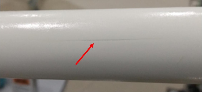
Install and inspect the Scan Window (For installation procedures, see Replacement-Gantry Enclosure-Gantry Scan Window Removal and Re-Install.)
-
Inspect the scan window for physical damage.
-
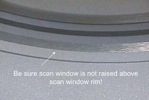
Check that the scan window is not raised higher than the front or rear cover at any location on the circle, and that the window is not wrinkled (see Figure 1).
Figure 1. Scan Window
-
Replace the scan window if it is damaged. (If you need to replace the scan window, follow the procedures in Replacement-Gantry Enclosure-Gantry Scan Window Removal and Re-Install to remove the old window and install a new one.)
-
-
Turn the 120 VAC power ON at the gantry service switch panel. (For procedures, see Safety-Equipment Service-Gantry.)
-
Rotate the gantry by hand and inspect rotational clearances.
-
Confirm Save System State completed successfully.
-
Turn ON the Axial and HV power switches at the gantry service switch panel.
-
Install the gantry side covers. (For installation procedures, see
14 Finalization
-
Complete the System Scanning Test. (For procedures, see System Scanning Test.) While completing the test, do the following verifications and record them on the PM Report Form:
-
Verify that the following X-ray On indicators light up:
-
SCIM /GSCB
-
Gantry Front
-
Gantry Rear (To avoid walking into the room during a scan, you may want to use a mirror to check this X-ray indicator.)
-
Room Warning Light
-
-
Verify that the following scan control push-button are operational:
-
Start scan (and keypad lights).
-
Stop scan (and keypad lights).
-
Pause scan.
-
Advance to scan.
-
Stop table.
-
-
-
Complete the Quality Assurance Test (For procedures, see Quality Assurance Test.)
-
Update the site logs. (For procedures, see Update Site Logs.)
-
Complete all required PM paperwork.