- Topic ID: id_15460284
- Version: 2.0
- Date: Nov 8, 2018 1:38:33 AM
ORP Replacement
Prerequisites
Overview
This document provides the necessary steps to replace and configure the Onboard Rotation Processor Unit (ORP) for imaging.
1 ORP Assembly Removal
Procedure
- Move table to home position.
- Remove gantry right side cover.
- Turn off [HVDC ENABLE], [AXIAL DRIVE ENABLE] and [120 VAC ENABLE] switches on Service Switch panel.
- Remove power to system. See Equipment Service - Lockout-Tagout-PPE from Safety section.
- Remove scan window, gantry left side cover, gantry top covers and gantry front cover.
- Rotate gantry such that ORP assembly is in 2 o'clock position.
- Engage rotational lock. See Equipment Service - Lockout-Tagout-PPE from Safety section.
- Disconnect four front cables and one rear cable from ORP Assembly.
- Detach and remove cable clamp from top of ORP Assembly with a 3mm Allen Wrench.
- Move cable bundle away from ORP Assembly in order to avoid damage during ORP Assembly removal / install process.
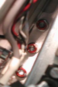
- Remove three M6 mounting screws from front of gantry with a
5mm hex bit socket drive and 12 inch extension (See Figure 1).
Figure 1. ORP Assembly Mounting Screws
- Remove ORP Assembly from gantry.
2 ORP Assembly Installation
Procedure
- Position ORP Assembly on to gantry and fasten with three M6 mounting screws.
- Tighten each M6 mounting screw with a 5mm hex bit socket torque
wrench and 12 inch extension, to the following torque values.
- Connect four front cables and one rear cable to ORP Assembly.
- Attach cable clamp to ORP Assembly top cover bracket and install harness into cable clamp.
- Secure cable clamp to ORP Assembly top cover bracket with a 3mm Allen Wrench.
- Disengage rotational lock. See Equipment Service - Lockout-Tagout-PPE from Safety section.
- Restore power to system. See Equipment Service - Lockout-Tagout-PPE from Safety section.
- From Console Unix Shell prompt, type touch /usr/g/fw/orpFtp and press ENTER.
- Turn on 120 VAC ENABLE, AXIAL DRIVE ENABLE, and HVDC ENABLE switches on Service Switch Panel.
- Press ESTOP RESET on Service Switch panel and wait until scan hardware is reset.
3 Setup, Checks, Alignments, and Calibrations
Procedure
- FLASH Download
- Gantry Rotation Safety Check
- Gantry Balance Procedure
- Turn off [HVDC ENABLE], [AXIAL DRIVE ENABLE] and [120 VAC ENABLE] switches on Service Switch panel.
- Install gantry front cover, gantry top covers, gantry left side cover and scan window.
- Turn on 120 VAC ENABLE, AXIAL DRIVE ENABLE, and HVDC ENABLE switches on Service Switch Panel.
- Press ESTOP RESET on Service Switch panel and wait until scan hardware is reset.
- Install gantry right side cover.
4 Finalization
Procedure
- Save Generator Runtime Parameters (See Save Restore Generator Runtime Parameters)
- Tube Warmup
- System Scanning Test
- Save System State