- Topic ID: id_15460294
- Version: 3.0
- Date: Jun 15, 2020 10:55:13 PM
Liquid Bearing Tube IB One-Time Upgrade for VCT
Prerequisites
Overview
This document explains the procedure of Liquid Bearing Tube IB upgrade for LightSpeed 7.X. This manual refers some procedures that already released (i.e. LFC procedure, Tube replacement procedure, etc.). Refer to LightSpeed 7.X Service Method (Gen.) CD-ROM (5193574-2EN rev.24 or later) in that cases.
There are two procedures. Two-Step upgrade procedure is used when LB Tube installation is done separately from Software upgrade and other hardware modification. One-Time upgrade procedure is used when both of Software upgrade, hardware modification and LB Tube installation are done at the same time.
System Requirement
LightSpeed 7.X with System software (12HW14.6 with any Service Pack) for GOC5, GOC6 and GOC6.5.
LightSpeed 7.X with System software (13HW31.8 with any Service Pack) for GOC6.6 Z820.
This procedure should be completed in conjunction with the VCT Liquid Bearing Tube FMI to ensure the update is documented and tracked.
Flowchart
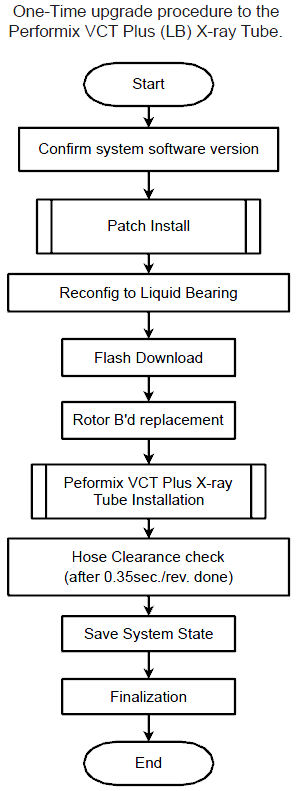
The following shows the flowchart used in this document.
Figure 1. Flowchart of One-Time Upgrade
Procedure
- Confirm that the software version is listed below.
-
12HW14.6, 12HW14.6_SP1-0-1 or 12HW14.6_SP1-1-1 (GOC5, GOC6, GOC6.5)
-
13HW31.8 or 13HW31.8_SP1-0-1 (GOC6.6 Z820)
-
-
(For GOC5, GOC6, GOC6.5) Execute (12HW14.6) Service Pack 2.2 Installation Procedure.
(For GOC6.6 Z820) Execute (13HW31.x) Service Pack 2.0 Installation Procedure.
Go to reconfig. menu and set Bearing type of X-ray Tube to “Liquid”. Refer to System Configuration (12HW14.6 SP2.1 or later).
- Perform Flash Download
- Using CSD > Utilities > Flash Download.
- Press “Update”.
- Once the Gantry Hardware Flash Downloads successfully, select [Dismiss].
- Replace Rotor B’d Replacement
- Remove Auxiliary Equipped.
Refer to the following section of LightSpeed 7.X Service method CD-ROM. Replacement > Gantry > High Voltage > Auxiliary Box Replacement
- Place the Auxiliary Box on a flat surface, then remove the front cover.
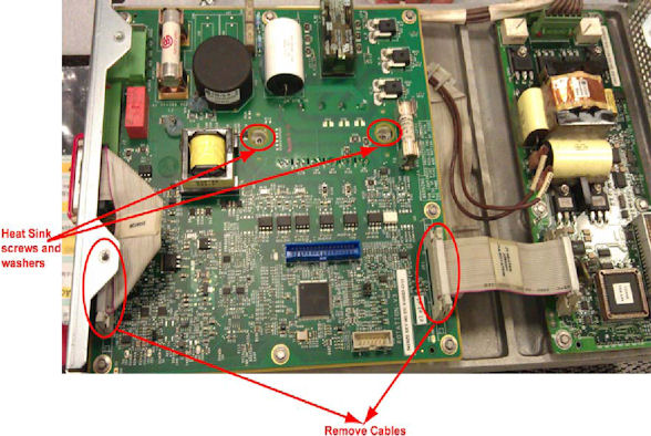
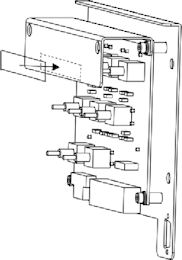
- Disconnect all cables to Rotor Control Board, unscrew all the
screws, and remove the old Rotor Control Board. Be sure to remove
screws and washers from heat sink also.note:
Use ESD/ground strap at rotor control board replacement.
Figure 2. Old Rotor Control Board Removal
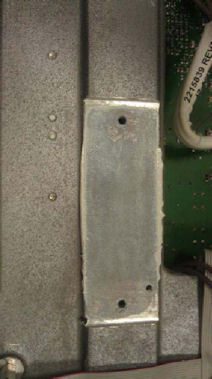
- Remove old thermal grease from groove.
Figure 3. Thermal Grease Removal
- notice
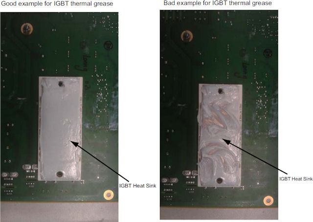
- Put on gloves and apply thermal conductivity grease (P/N 5134927)
on IGBT heat sink of the new rotor board (P/N 5456518), then install
the new rotor board to Auxiliary Box and re-connect cables.
Figure 4. Rotor control Board IGBT Heat Sink
- Torque the two screws to the following final value. Install
the RCB with 8 screws.
Figure 5. Rotor Control Board

- Re-install the front cover of Auxiliary Box.
- Attach “2324118-9” label on the modified auxiliary
equipped.
Figure 6. Label Location of Auxiliary Box
- Install modified Auxiliary Equipped. Refer to the Auxiliary Box Replacement .
Do not install stator cable at this time because the cable will be disconnected again at Tube replacement procedure.

- Remove Auxiliary Equipped.
- Install the Performix VCT Plus Tube. Refer to Tube Replacement (VCT LB Tube).
- Interposer plate must be replaced with new one provided in LB
Tube Upgrade kit during Tube replacement procedure. The following
shows the procedure.
- Remove three M4 hex screws and replace the current interposer
plate with provided one (remove three flat head screws). Position
the interposer plate at approximate center of circle in picture (slot
hole). New interposer plate uses only one flat head screw to fix it.
Refer to the following Illustrations.
Figure 7. Three hex screws for interposer plate
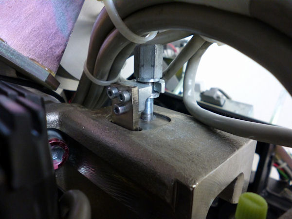
Figure 8. New interposer plate
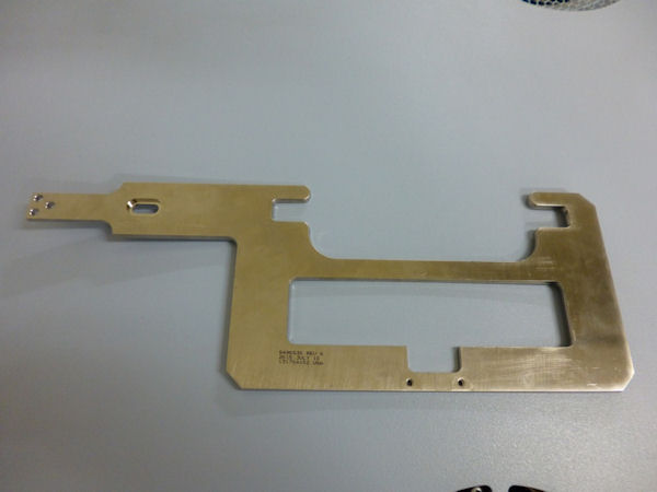
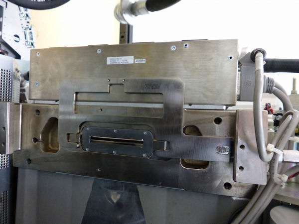
Figure 9. Interposer plate with collimator
- Apply loctite 243 for the three hex screws and one flat head screw.
- Keep original interposer plate and two flat head screws for future use.
- Remove three M4 hex screws and replace the current interposer
plate with provided one (remove three flat head screws). Position
the interposer plate at approximate center of circle in picture (slot
hole). New interposer plate uses only one flat head screw to fix it.
Refer to the following Illustrations.
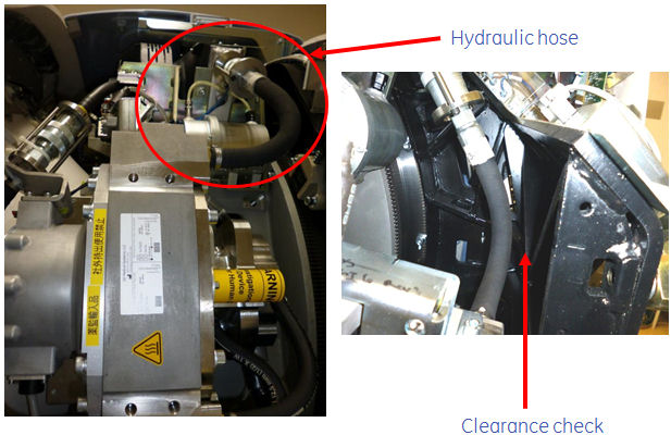
- Make sure of a clearance between the hydraulic hose and gantry
frame again.
Especially confirm the clearance around hose of heat exchanger.
Figure 10. Clearance check point (Gantry right side view)
- Perform Save System State
- Using CSD > Utilities > System State.
- Insert DVD or USB memory and press “Save System State”.
- Press “Dismiss” when it’s completed.
Finalization
- Perform sanity scan with the following technique and confirm
they completed successfully.
Scout, Axial and Helical.
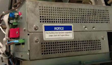
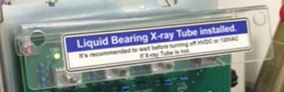
- Attach the labels (on Service Switch Panel, PDU and A1 Panel)
of Label collector (P/N 5788095) provided in FMI kit (part of Liquid
Bearing upgrade kit), follow to the instruction in the Label collector.
Figure 11. Location of Liquid Bearing Tube Label
- Install Gantry right side cover.
- Discard old service pack CD-ROM.
- Send the following information to Performix.Plus@ge.com
Liquid Bearing Tube serial number
LB Tube Installation date
LB Tube kAs
LB Tube exams
System ID