- Topic ID: id_15460607
- Version: 2.0
- Date: Nov 8, 2018 1:38:26 AM
Auxiliary Box Replacement
Prerequisites
Overview
This document provides the necessary steps to replace and configure the Generator Auxiliary Box for imaging.
1 Auxiliary Box Removal
Procedure
- Move table to home position.
- Remove right side gantry cover.
- Turn off [HVDC ENABLE], [AXIAL DRIVE ENABLE] and [120 VAC ENABLE] switches on Service Switch panel.
- Remove power to system. See Equipment Service - Lockout-Tagout-PPE from Safety section.
- Remove scan window, gantry left side cover, gantry top covers and gantry front cover.
- Rotate gantry such that Auxiliary Box is in 2 o'clock position.
- Engage rotational lock. See Equipment Service - Lockout-Tagout-PPE from Safety section.
- Cut Ty-wraps on Inverter and Auxiliary Box clamps and remove High Voltage cable from clamps.
- Carefully move High Voltage cable towards gantry front and away from Auxiliary Box.
- Detach cable clamps from Auxiliary Box front panel with a 3mm
Allen Wrench.note:
Keep clamp hardware pieces.
- Disconnect seven cables from Auxiliary Box front panel.
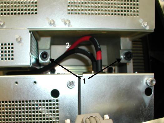
- Remove two M12 mounting bolts from gantry right side with a
10mm hex bit socket drive and 12 inch extension ( See Item 1 in Figure 1).note:
Remove bolts and washer out to ease Auxiliary Box removal.
note:If bolts are supplied with new Auxiliary Box, throw away old bolts and washers.
note:If bolts are not supplied with new Auxiliary Box, reuse existing bolts and washers. Make certain to thoroughly clean all dried Loctite from bolts.
Figure 1. Auxiliary Box Mounting Bolts and HVDC Cables
- Remove Auxiliary Box by lifting up and pulling out, towards gantry right side.
- Detach High Voltage cable clamps from Auxiliary Box front and
top panels with a 3mm Allen Wrench.note:
Keep clamp/bracket hardware pieces.
2 Auxiliary Box Installation
Procedure
- Attach High Voltage cable clamps to Auxiliary Box front and top panels with a 3mm Allen Wrench.
- Position Auxiliary Box over Inverter mounting bracket.note:
Route HVDC wires between Auxiliary Box and Inverter ( See Item 2 in Figure 1).
note:Use Auxiliary Box chassis slots as positioning guides.
- Apply blue Loctite (242) to each M12 mounting bolt.note:
If bolts are not supplied with new Auxiliary Box, reuse existing bolts and washers. Make certain to thoroughly clean all dried Loctite from bolts and apply new blue Loctite (242).
- Fasten Auxiliary Box with two M12 mounting bolts and washers.
- Tighten each M12 mounting bolt with a 10mm hex bit socket torque
wrench and 12 inch extension, to the following torque values.
- Connect seven cables to Auxiliary Box front panel.
- Attach cable clamps to Auxiliary Box front panel with a 3mm Allen Wrench.
- Position High Voltage cable into each High Voltage Inverter and Auxiliary Box clamp.
- Secure High Voltage cable to each clamp with a Ty-wrap.
- Disengage rotational lock. See Equipment Service - Lockout-Tagout-PPE from Safety section.
- Restore power to system. See Equipment Service - Lockout-Tagout-PPE from Safety section.
- Turn on 120 VAC ENABLE, AXIAL DRIVE ENABLE, and HVDC ENABLE switches on Service Switch panel.
- Press ESTOP RESET on Service Switch panel and wait until scan hardware is reset.
3 Setup, Checks, Alignments, and Calibrations
Procedure
- Gantry Rotation Safety Check
- Gantry Balance
- Tube Warmup
- HHS Scans
- Turn off HVDC ENABLE, AXIAL DRIVE ENABLE, and 120 VAC ENABLE switches on Service Switch panel.
- Install gantry front cover, gantry top covers, gantry left side cover and scan window.
- Turn on 120 VAC ENABLE, AXIAL DRIVE ENABLE, and HVDC ENABLE switches on Service Switch panel.
- Press ESTOP RESET on Service Switch panel and wait until scan hardware is reset.
- Install right side gantry cover.
4 Finalization
Procedure
- System Scanning Test
- Save Generator Runtime Parameters (See Save Restore Generator Runtime Parameters)
- Save System State