- Topic ID: id_15460179
- Version: 4.0
- Date: Jan 20, 2020 8:35:07 PM
DAS Fan, Fan Plate Assembly Replacement
Prerequisites
Overview
This procedure defines the information necessary to properly remove and replace a fan or fan plate assembly. Individual fans may or may not be spare part.
1 Procedure Steps
Procedure
- Remove the Gantry Right side cover.
- Stop the rotor of X-ray tube in case of Liquid Bearing Tube before HVDC off. Refer to Liquid Bearing Tube Rotor stop procedure for details.
 danger
- Disable Axial Drive and HVDC service switches on the service switch panel.
- Position the DAS/Detector at 12 o’clock and lock gantry rotation.
- Shut down power to the rotating assembly using the Service Switch
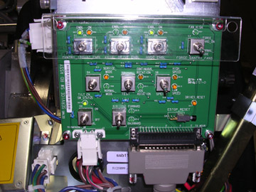
panel 120 VAC service switch. See Figure 1.
Figure 1. Service Switch Panel
- Remove gantry left side, top and front covers.
Refer to
2 Removal
Procedure
- Disconnect the fan control cable from the fan plate and loosen
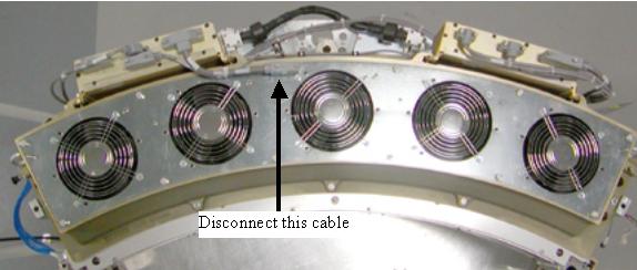
captive screws holding the fan plate to the Air plenum. See Figure 2 for VCT Plenum front view. See Figure 3 for 2006 style Plenum changes. Remove the single cable connection
on the fan plate for the 2006 style Plenum.
Figure 2. VCT Detector Plenum
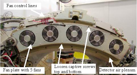
Figure 3. VCT Plenum 2006 Style Changes
- Lift off the fan plate. The entire plate or individual fan can now be replaced.
3 Installation
Procedure
- If replacing a single fan, Install new fan onto the plate and
torque nuts to:
- Install the fan plate assembly. There are guide pins on each
end of the plenum casting.note:
Be careful not to pinch wires or harnesses between the fan plate and the air plenum casting.
- Torque fan plate screws to:
- Reconnect fan control cable.
- Turn on the 120 VAC service switch at the service switch panel. Check to make sure all 5 fans are running. Use a piece of paper or similar object to make sure fans are pulling air into the plenum. A fan that is not running will still have the fan blades moving as air is pushed back out of the plenum through that fan port.
- Turn off the 120 VAC service switch, release the gantry rotational
lock and install gantry covers, all except the right side cover.
Refer to
- Turn on the 120 VAC, HVDC and Axial drive service switches.
- Install gantry right side cover.
4 Finalization
Procedure
- If any calibrations were run with a fan not working (Fastcal or Detailed Calibration), those calibrations will need to be run after repair is complete.
- Perform the Quality Assurance Test.
- Perform a Save State operation if Detailed Calibrations were performed.