- Topic ID: id_11038750
- Version: 4.0
- Date: Apr 22, 2019 12:56:10 AM
Collimator Control Board (CCB) Replacement
Prerequisites
Overview
This document provides the necessary steps for replacing the Collimator Control Board.
Procedure
- Remove side, top, and front gantry covers.
- Stop the rotor of X-ray tube in case of Liquid Bearing Tube before HVDC off. Refer to Liquid Bearing Tube Rotor stop procedure for details.
- Turn OFF the Axial Drive and HVDC switches on the gantry’s Service Switch Panel.
- Position the tube at 6 o'clock.
- Turn OFF the 120VAC switch on the gantry’s Service Switch Panel.
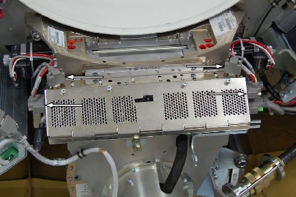
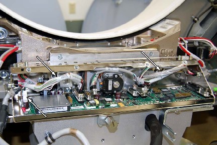
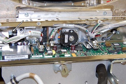
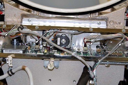
- Disconnect CAM encoder harness at the CCB chassis for both CAM
motors and also disconnect CAM power harness at the CCB chassis for
both CAM motors.
Figure 1. Harness Connectors
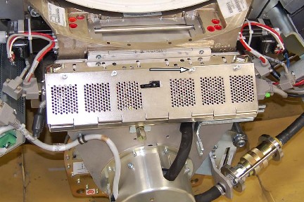
- Cut the tie-wraps that secure the wiring harness of the CCB
chassis (usually has 6).
Figure 2. Tie-wraps
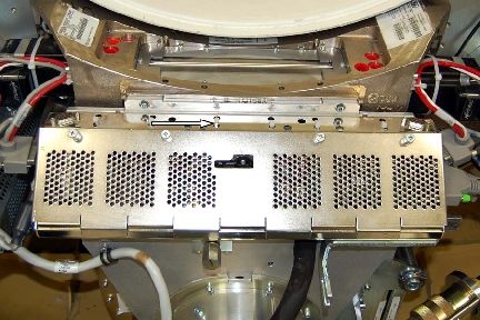
- Loosen the four (4) thumb-screws holding the front CCB chassis
cover and remove the cover.
Figure 3. Four CCB Cover Screws
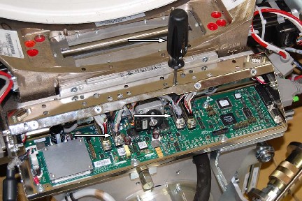
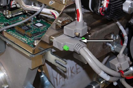
- Disconnect connectors J3 and J4 filter motors and encoders from
the CCB. Use access holes in chassis for back screws.
Figure 4. J3 and J4 - disconnecting
- Position the CAM cables out from the CCB / Chassis assembly,
and disconnect the power cable.
Figure 5. Cam Cables
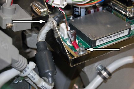
- Remove the ground screw and disconnect the grommet.
Figure 6. Ground and Grommet
- Disconnect collimator connector J7.
Figure 7. Collimator J7
- Remove cable clamp screws holding filter motor leads.
Figure 8. Cable Clamp
- Remove the four (4) M6 screws holding the CCB/Chassis assembly
to the collimator.
Figure 9. CCB Chassis Mounting Screws
- To Install new CCB, Carefully route the wire harnesses through the CCB and position the CCB Chassis assembly.
- Install the four (4) mounting screws.
- Position the filter motor leads and install the cable clamp screws.
- Connect collimator connector J7 and torque to 3.0 Nm (26.6 lb-in).
- Position the grommet and ground wire, install the ground screw.
- Connect the power cable and reposition the cables inside the chassis.
- Connect J3 and J4 connectors and torque to 3.0 Nm (26.6 lb-in).
- Install the six (6) new tie-wraps securing the wiring harness.
- Connect the CAM encoder and power harnesses at the cam motors.
- Install the chassis cover.
- Turn ON the 120VAC, Axial Drive and HVDC switches on the gantry’s Service Switch Panel.
- Install all the covers.
Finalization
- For new CCB, system should auto-detect new CCB to synchronize system proper characterization file / serial number. Follow on-screen instructions.
- For new CCB, it may be necessary to run Flash Download.
- For new CCB, perform:
Save System State