- Topic ID: id_15460223
- Version: 2.0
- Date: Nov 8, 2018 1:37:14 AM
06MW29.7 SW LFC (LS 7.X)
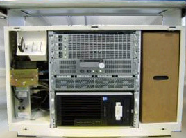
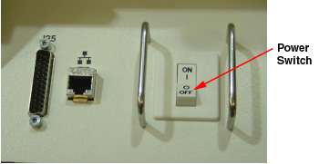
Figure 1. LightSpeed 7.X GOC5 Operator Console (Front Cover Removed)
For equivalency of PDF vs. HTML versions of this procedure (i.e, 5116412-100 vs. this publication), please compare procedure “Last Revised Dates.”
(For For equivalency of PDF output) The contents of this chapter are equivalent to the LFC procedure “06MW29.7 LFC (LS 7.X)” (file “762195.htm”), found under “Software” > “Software Installation Procedures (LFC)” on CD-ROM 5116423-200, Revision 12.
1 Scope
This LFC (Load from Cold) procedure supports systems using version 06MW03.4 or later.
2 Preliminary Requirements
2.1 Software Version (For LightSpeed 7.X) 06MW29.7
This Procedure applies to the software version 06MW29.7 or later.
-
5154896 - LightSpeed Xtream Console Operating System
Version - GEMS Linux 4.3.16
-
5182028 - LightSpeed Applications Software DVD
Version 06MW29.7
-
5193458 - Xtream Serial-Over-LAN Service Software
Version - 2.0 Supports: Westville or Jarrell DARC/VDARC
-
5192389 - Limited Access Software
The Xtream Serial-Over-Lan Service Software is not used during the LFC unless instructed via a pop-up message box "SOL Service - ...run the Serial Over LAN Service CD...". This CD is loaded directly into the VDARC Node. Then press the reset (or cycle power) at the front panel of the VDARC Node as required. This CD will auto-eject when the SOL load process is complete.
2.2 Hardware
-
Verify the SCSI Tower DVD-RAM power is applied.
-
Verify the SCSI Tower terminator LED is lit (located at the rear).
-
Verify the Host Computer DVD-ROM drive does not have any media in it.
-
Verify and record specific system hardware configuration.
Record screen information in VCT Console Information Sheet.
-
Open a Unix Shell and type the following:
{ctuser@ hostname } swhwinfo -a
-
Record software version.
-
Type the following:
{ctuser@ hostname } su -
{ctuser@ hostname } #bigguy
{root@ hostname } dmidecode | grep -i version
BIOS Information (Command is available with 05MW31.5X)
Version: JQ.W1.13.US = 1.13 for xw8000
Version: 786B8 v2.10 = 2.10 for xw8200
note:If you have an xw8200 that does not have 2.10 BIOS, continue the LFC and order the 2.10 BIOS Floppy (P/N 5191771) to update the Host later.
(For GE Healthcare Personnel Only) The BIOS update is also available via Support Central.
-
Record bios version.
-
Type the following:
{root@ hostname } exit
{ctuser@ hostname } cat /usr/g/config/INFO
-
Record screen information asked for in the VCT Console Information Sheet.
-
-
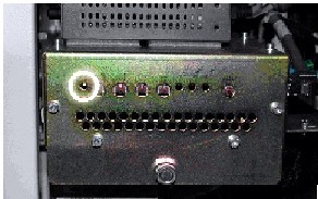
Verify the ICOM has the power LED lit. (See illustration, below.)
-
Record Tube number of Exams and Tube Install Date. This information can be found under System Information or can be found as follows:
-
Open the Service Desktop.
-
Select Error Logs.
-
Select Tube Usage.
-
Select Details.
-
3 Procedures
3.1 Save System State
 |
|
New tasks are included in this SW release. These tasks will generate data that needs to be saved to the System State DVD. Follow the save and restore procedures throughout this document precisely or valuable information may be lost.
This process takes approximately twenty (20) minutes, but in some cases may take up to thirty (30) minutes.
-
Insert the System State DVD-RAM into the SCSI Tower DVD RAM drive.
-
Wait until the DVD drive is ready (i.e., until the front panel green LED is no longer lit).
-
Select: Service icon to access the CSD (Common Service Desktop)..
-
Select: Utilities.
-
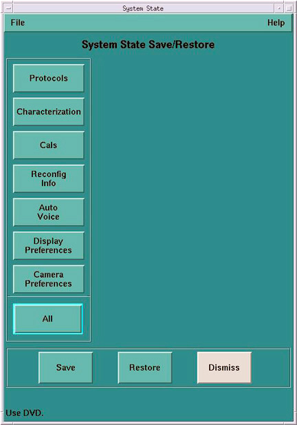
Select: System State.
-
Select All to select all the cals, characterizations, etc.
-
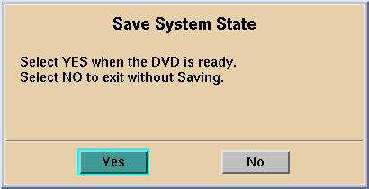
Select Save.
-
If applicable, select Yes when the following message appears: System State Media Status: Please insert a DVD into the drive and press Save again.
 note:
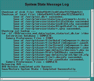
note:Verify that the "Save" of System State was successful. If not, correct any errors and re-save the system state. A message at the end of the Save should state: Save/Restore System State: Completed Successfully.
-
When completed, select CANCEL.
-
When completed, select Dismiss.
IMPORTANT: Do NOT select DISMISS more than once. Doing so will result in the GUI becoming hung, and the System State will be unusable. Should this occur, Save System State again.
-
Close the Service Desktop window at the upper left corner of the screen.
3.2 Load from Cold Procedures
Use these procedures to perform a “Load from Cold” (LFC) from a grouping of Software media.
Before proceeding you must disconnect the console from the Hospital Network. Failure to do this may result in the console broadcasting traffic out to the entire Hospital network.
3.2.1 Disconnect Hospital Network Cable from Rear Console Bulkhead
-
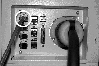
Unplug the Hospital Network (HSP) cable from rear Console bulkhead. See illustration below.
-
Label the cable appropriately and set it aside during LFC.
3.2.2 Linux Operating System (OS) Software Load on Host Computer
System State SAVE must be performed before performing the Load From Cold Procedure.
-
Remove the Operator Console's front cover.
-
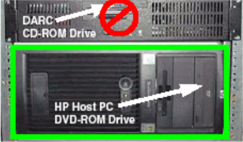
Insert the OS DVD into the Host Computer DVD-ROM drive (see the illustration below). The Host Computer must be powered ON to insert the disk.
-
Select one of the following methods to re-power the Operator Console:
-
If Applications are up:
-
Select the Shut Down button.

-
Select Restart then OK to restart the system.
-
-
If Application Software is down, at the toolchest open a Unix Shell and type:
-
{ctuser@ hostname } sync
-
{ctuser@ hostname } sync
-
{ctuser@ hostname } halt
note:(For 06MW03.X Software) NOTICE: Wait 1-2 minutes after the “System halted” message appears, to allow the DARC Node to properly power-down. Future SW releases (e.g., 06MW29.7) have corrected this issue.
-
The Operator Console monitor will display a System Halted message when it is acceptable to power OFF the Operator Console.
-
Power OFF the Operator Console at the front panel switch.
-
Wait 30 seconds to allow the disk drive to settle; then power ON the Operator Console at the front panel switch.
-
-
-
As the Host Computer restarts, the booting process messages appear. After the booting process completes, the boot: prompt appears. (The OS is a bootable media.)
-
At the boot: prompt, type one of the following depending on system type:
GEHC2 (for English Keyboard only)
iGEHC2 (International command only)
note:The Console Operating System load takes approximately 20 minutes. If the boot: prompt does not appear, then either the DVD is bad or the Console Operating System Media is not installed in the drive. Typing GEHC (or iGEHC) results in both scan and display being on one monitor and requires a LFC. Typing any other command not listed in this procedure will result in a LFC.
-
After the OS is loaded on the Host Computer, a red button appears and displays Reboot.
-
Remove the OS DVD from the Host Computer DVD-ROM Drive when it ejects.
-
Press Enter to reboot.
-
The Host Computer will reboot.
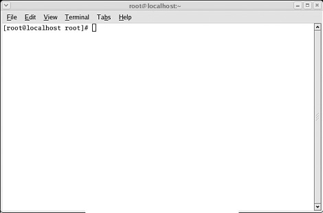
note:Do not insert the LightSpeed VCT Applications Software DVD into the Host Computer until the system reboots and the [root@localhost] window appears, displaying the [root@localhost root]# prompt.
3.2.3 Application Software Load on the Host Computer
There is a single Application DVD used for both the Host Computer and the VDARC. All applications software will be loaded to the Host Computer during this process.
|
|
-
Verify VDARC Trouble Shooting cable is not connected to the Scan or Display Monitors at this time.
-
After the Host Computer reboots, verify that the window appears with the [root@localhost root]# prompt.
-
Insert the Applications DVD into the DVD-ROM drive on the Host Computer. See the illustration below.
-
After approximately 15 seconds, a pop-up box appears, displaying:
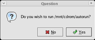 note:
note:If the pop-up box Question does not appear after two minutes, type the following and wait approximately one minute for the pop-up box to appear.
mount /mnt/cdrom
/mnt/cdrom/autorun
-
Select Yes to run /mnt/cdrom/autorun.
-
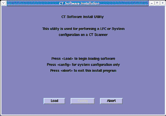
After approximately 15 seconds, an Installation Utility window appears. (See Figure 2)
Figure 2. Installation Utility Window
-
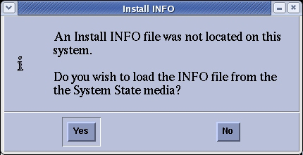
Select LOAD button. A prompt message appears asking if you want to load the INFO file from the System State DVD.
-
System State DVD:
-
If you do not have a System State or the System State is unusable, select NO.
-
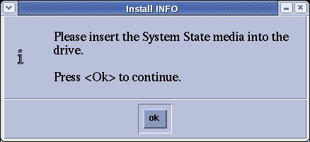
If you have a System State DVD, select YES. When prompted, ensure the System State DVD is in the DVD drive in the SCSI Tower (on top of the console), and then select OK.
-
-
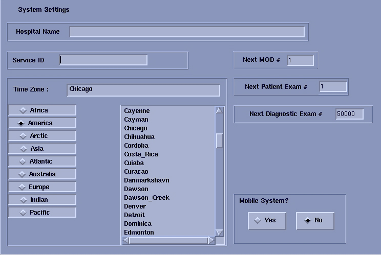
Select the System tab.
See example System Settings screen, below.
-
Verify that the Next Patient Exam # on the System Settings screen is the value restored from Save System State. Otherwise, set to 1.
-
Verify that the proper Time Zone is selected.
-
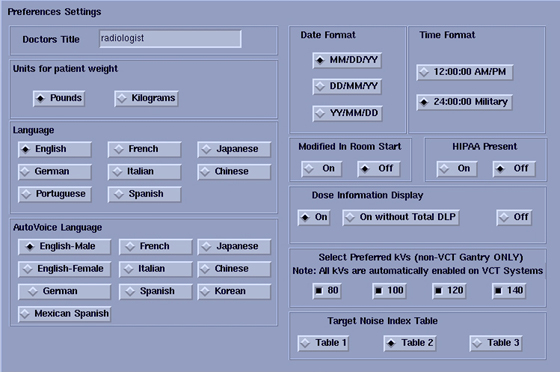
Select the Preferences tab.
See the illustration below, for an example Preference Settings screen.
-
Select the units for Patient Weight.
-
Select Language: (ENGLISH or OTHER).
-
Select Preferred FastCal KV - select the kV to be calibrated during FastCal. These kVs should include all kVs that the site uses for patient scanning.
note:For VCT, all kV's are automatically enabled.
-
Select Target Noise Index Table.
-
Verify proper Date Format is selected.
-
Verify proper Time Format is selected.
-
Verify Modified in Room Start is set to OFF, unless the site is in Japan, and/or the customer has requested that this be turned ON.
-
Set HIPAA Present to OFF, unless the customer requests HIPPA to be ON.
-
Select the site preferred Dose Information Display option for the site to use in monitoring calculated Patient Dose:
-
Select ON (full CTDiw Display)
-
Select ON WITHOUT TOTAL DLP (no Dose Length Product Display), or
-
Select OFF (no CTDIw Display)
note:A scroll bar below this menu may be present. It contains the System Information from the INFO file System State.
-
-
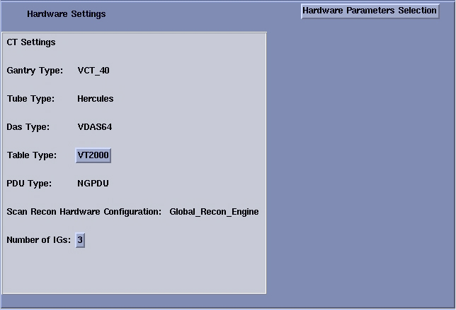
Select the Hardware tab.
See example Hardware Settings screen, below.
-
Select the Hardware Parameters Selections button. Then, depending on the VCT site, select one of the following:
-
VCT64/32 BL
-
VCT32 FL
-
VCT HALO 64
-
-
Select the proper Table Type for Hardware.
See example Hardware Settings screen, below.
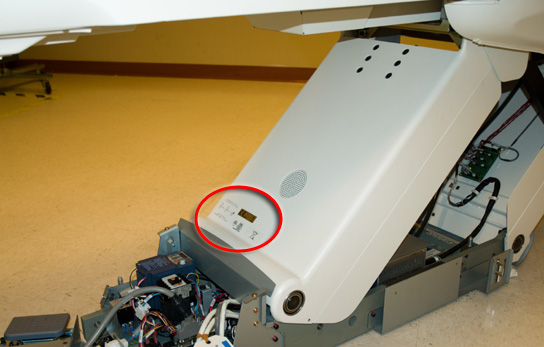
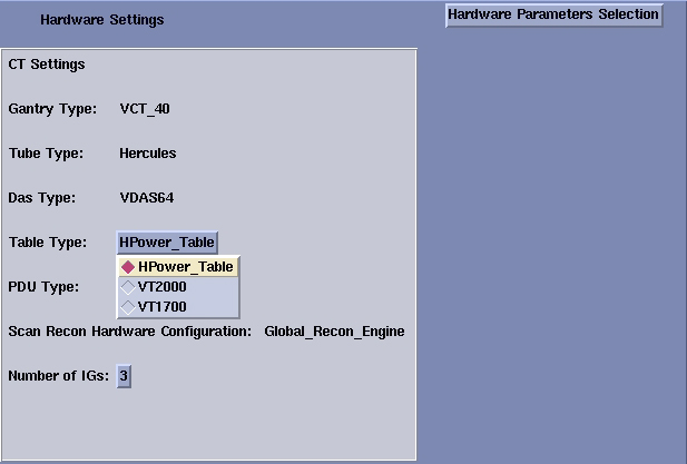 note:
note:Check the label/rating plate at the front bottom of the Table, closest to the Gantry (by the GTCB), and determine the Table Type according to the part number of the Table:
-
5121647: VT2000
-
5122080: VT1700
The HPower_Table selection is not valid for VCT Installed Base
-
-
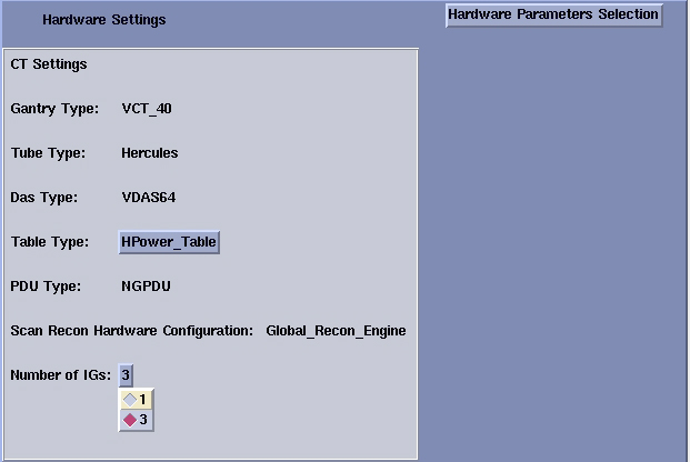
Select the proper Number of IGs present in the Operator Console.
See example Hardware Settings screen, below.
-
Select the Network button.
See example Network Settings screen, below.
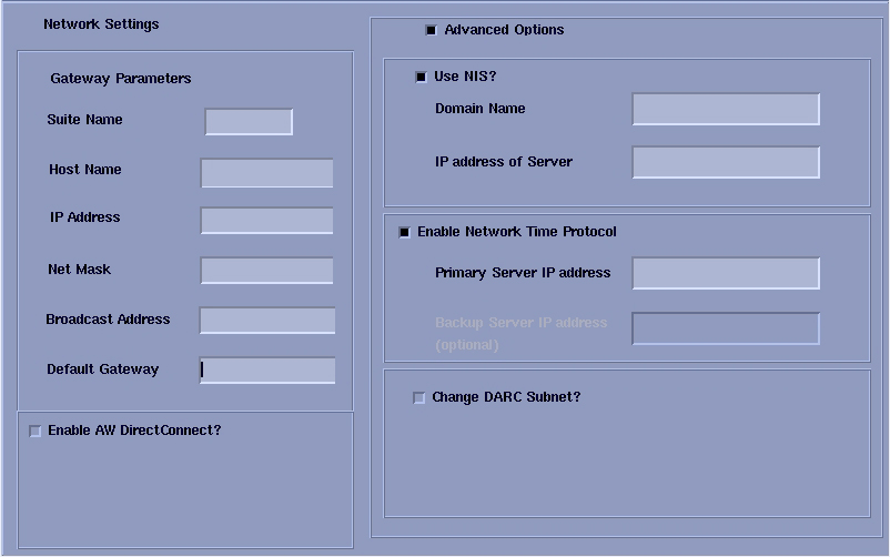
-
Configure Network Settings:
-
Suite Name - Add your name here.
note:The Suite Name must start with a letter, followed by 3 alphanumeric characters. Total must be four characters long. The name of the OC interface <Suite Name>_oc within the scanner's subnet. It is suggested that you choose CT01 as its name, unless a different Suite Name is required. The Suite Name must be uppercase.
-
Host Name - Add your host name here.
note:The Host Name identifies the hostname and AE Title of the scanner. It:
-
MUST NOT be <Suite Name>_oc or <Suite Name>_OC.
-
MUST NOT exceed 16 Characters.
-
MUST only contain the following characters: a thru z, 0 thru 9, - and _.
-
-
IP Address - Site supplied address.
-
The following procedure should be performed if your customer Ethernet hospital backbone begins with 172.16.0.xx, OR if the scanner will connect to a device with an IP address of 172.16.0.xx.
-
If hospital backbone starts with 172.16.0.xx and this is a first time install, change the VDARC subnet by checking the Change DARC subnet box, and fill in the following value: 169.254.0. Continue and complete the software load on the HOST and VDARC.
-
If the hospital backbone starts with 172.16.0.xx, and the VDARC subnet was already changed, verify that the Change DARC subnet box is checked and a subnet is already filled. Continue and complete the software load on the HOST and VDARC.
-
If the VDARC subnet was already changed and needs to be set to the 172.16.0 subnet, deselect the Change DARC subnet box. Continue and complete the load on HOST and VDARC.
-
-
Net Mask - Site supplied address.
note:If the hospital backbone IP address is 192.9.220.xx, then the Net Mask must be set to 255.255.255.252.
-
Broadcast Address - Site supplied address.
-
Default Gateway - Site supplied address.
note:Make sure the NUM LOCK button on the keyboard is not active. If it is, deselect it to enable the ACCEPT button in the next step. Failure to deactivate the NUM LOCK results in load issues.
-
If your customer has AW Direct Connect, then select Enable AW DirectConnect?. Complete the LFC, making certain to configure this feature in AW Direct Connect. (Do not configure AW Direct Connect now.)
-
If your customer wants to synchronize the system time to their NTP server, then select Enable Network Time Protocol, and enter the Primary Server IP address.
-
-
Select the PET tab and make sure the PET option is disabled.
-
Select the ACCEPT button at the right corner of the User Interface.
-
An Install INFO pop-up box is displayed.
See illustration below, for a typical Install INFO message (the Install INFO message is different for each system configuration).
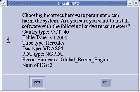
-
Select yes, if correct.
note:If the information is not correct, select the NO button. This returns you to the Hardware screen. Select the Hardware Parameters Selection button and select the correct system configuration from the displayed list. Select the Accept button again, followed by the YES button on the Install INFO pop-up to accept the new hardware configuration.
-
The following pop-up message appears:
Please make sure the CT Application SW is in the drive - the system will be rebooted.
No action is required for this pop-up. The system will automatically reboot after approximately 10 seconds if the OK button is not selected.
note:Do not remove the Applications DVD from the Host Computer until instructed to do so.
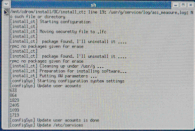
-
As the system reboots, the following Winterm window message appears: Starting LFW procedure. A shell Installation screen appears and the application software starts loading.
-
When the system prompts you to reboot (after approximately 13 minutes), answer YES. The system is going down for reboot NOW. (See illustration, below.)
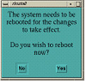 note:
note:During the reboot of the console, a message may appear to the effect that the system was not able to determine what the tube type was and to run the TIC tool. This message should be ignored.
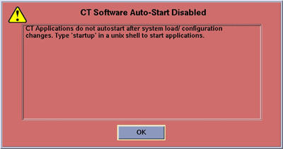
-
After approximately 3 minutes, a pink pop-up box appears, stating CT Software Auto- Start Disabled. In this box, select OK.
-
Press the button on the DVD-ROM drive to remove the Applications DVD from the Host Computer.
-
Open a Unix Shell. Type the following:
{ctuser@ hostname } su -
{ctuser@ hostname } #bigguy
[root@ hostname ]# setdate
Note: Type “q” to quit anytime. Enter to proceed:
Note: TO BE ACCURATE, this tool will prompt you to enter the “Second”. Watch your clock or PC carefully to enter the proper value, and hit [Enter] at the right second to set the accurate time. Enter to proceed:
Enter the current Year (1980-2030) [2006]:
Enter the current Month (1-12) [04]:
Enter the current Day (1-30) [14]:
Enter the current Hour (Military Time) (0-23) [18]: 15
Enter the current Minute (0-59) [13]: 18
Enter the current Second (0-59) [00]: 10
\nUpdating the time on the OC and SBC, Please Wait...
PING darc (172.16.0.2) 56(84) bytes of data.
Current OC date : Fri Apr 14 15:18:00 CDT 2006
Could not retrieve the SBC TImeZone.
Please make sure the TimeZones for the OC and SBC are the same.
[root@ hostname ]#
-
Upon completing the above command, the user will receive one of the two following responses:
-
If the VDARC Node has been replaced and has no software, the following response will appear:
--- darc ping statistics ---
1 packets transmitted, 0 received, 100% packet loss, time 0ms
The darc is not responding. darc will sync time with oc during next darc reboot
Current OC date : Fri Apr 14 15:18:00 CDT 2006
Could not retrieve the SBC TImeZone.
Please make sure the TimeZones for the OC and SBC are the same.
[root@ hostname ]#
-
If the VDARC Node is being reloaded and had software, the following response will appear:
--- darc ping statistics ---
1 packets transmitted, 1 received, 0% packet loss, time 0ms
rtt min/avg/max/mdev = 0.139/0.139/0.139/0.000 ms, pipe 2
connect to address 10.0.1.2: Connection refused
connect to address 10.0.1.2: Connection refused
trying normal rsh (/usr/bin/rsh)
connect to address 10.0.1.2: Connection refused
connect to address 10.0.1.2: Connection refused
trying normal rsh (/usr/bin/rsh)
Current OC date : Fri Apr 14 16:14:05 CDT 2006
Current DARC date : Fri Apr 14 16:14:04 CDT 2006
setdate completed with NO ERRORS.
[root@ hostname ]#
-
3.3 DARC Software Load Process
3.3.1 Confirm Host PC Software
Confirm the Host Computer Software type. The software section of the version output should match example shown.
-
Open a Unix Shell and type the following to see software and hardware Config information.
{ctuser@ hostname } swhwinfo
06MW29.7 <hardware revision info here>
Example: 06MW29.7.V40_H_V64_G_GTL
note:-
If the revisions match, continue with this procedure.
-
If the revisions do NOT match, reload the software.
-
-
{ctuser@ hostname } swhwinfo –o for OS version
Release: GEHC/CTT Linux 4.3.16
Built: Tue Jul 12 12:29:10 CTD 2005
note:Confirm that the results match the Operating System version and Software Build Date shown on the OS and Applications DVDs.
3.3.2 Operating System Software Installation on Host Computer for VDARC
The OS DVD will be inserted into the Host Computer, and it will be loaded to the VDARC Node via a script.
For details on Serial Over LAN CD Usage, refer to VDARC/DARC Node OS Load Troubleshooting.
If additional problems arise, verify the correct media is installed or verify the Boot BIOS Order is correct. If VDARC Node OS load problems continue, perform the VDARC Stand-Alone OS Load procedure. This stand-alone procedure eliminates any external sources causing an issue but does not rule out media issues or internal VDARC Node issues.
-
Power on the VDARC and VIGs by pressing the power button on the VDARC and VIGs, respectively.
-
Open a Unix Shell and type the following:
-
{ctuser@ hostname } su -
-
Password: #bigguy
-
[root@ hostname ] cd /usr/g/scripts
-
[root@ hostname ] ./start_darcOS
-
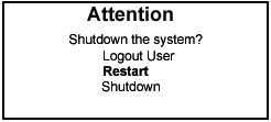
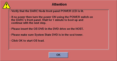
An Attention window appears:
Figure 3. Attention Window
-
-
Follow the instructions in the Attention window:
-
Verify the VDARC Node is turned ON
-
Insert the OS DVD into the Host Computer DVD-ROM drive
-
Select OK to begin.
note:If the DARC OS Load Fails, a Pop-Up will inform the user to set the DARC BIOS Order. (Refer to Change VDARC BIOS Boot Order Settings.)
-
-
An sh window displays the message below followed by a series of rows of dots.
Copy OS packages from the DVD to the HOST’s hard drive. This takes about 10 minutes.………………………………………………………………………….
………………………………………………………………………….
………………………………………………………………………….
………………………………………………………………………….
-
Once the copy process is complete the OS load begins:
OS load has started. This takes about 15 minutes.
##.## % done.
note:The VDARC OS Load will stop prematurely ONLY if an error is encountered (refer to VDARC/DARC Node OS Load Troubleshooting). An Error Dialog Box will appear with a brief description of the error. Select OK after reading the instructions displayed on the Monitor. Refer to DARC OS Load Pop-Up Boxes for information on additional error pop-up windows. Also, if any problems arise, verify the correct media is installed.
note:A %done status is displayed during the VDARC OS load. This is only a timed countdown sequence and does not provide status of the actual load process. When the VDARC OS load has completed a reboot message will appear.
-
Once the load process is complete the DARC reboots:
Waiting for the DARC to boot up…
-
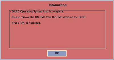
When the VDARC OS load has completed, a pop-up Information box is displayed. An example is shown below.
-
The OS disk will eject automatically. Remove the OS media from the Host Computer drive and close the drive.
-
Select OK.
-
To verify the OS has been loaded on the VDARC Node, open a Unix Shell and type the following:
note:If the VDARC login prompt [root@localhost root] is not present, then try reloading the VDARC Node OS again per the procedure. Always be sure the VDARC OS matches the Host OS already loaded. If issues persist perform the VDARC Stand-Alone OS Load procedure.
-
{ctuser@ hostname } su -
-
Password: #bigguy
-
[root@ hostname ] rsh darc
-
[root@localhost root] exit
-
-
This completes the OS load for the VDARC Node.
3.3.3 VDARC Applications Software Load
The Applications DVD is not required to be in the DVD drive for VDARC Applications to load.
-
Open a Unix Shell and type the following:
[ctuser@ hostname } su -
Password: #bigguy
[root@ hostname ] cd /usr/g/scripts
[root@ hostname ] ./start_darc_load
-
A shell window pops up and the load begins. A SUCCESSFUL LOAD TAKES ~10 MINUTES. Continue the procedure when the load window goes away.
-
Close the shell (do not use for the next process).
3.4 Reboot The Operator Console & Stop Application from Starting Up
Open a Unix Shell and type the following:
-
[ctuser@ hostname } su -
-
Password #bigguy
-
[root@ hostname ] sync
-
[root@ hostname ] sync
-
[root@ hostname ] reboot
A message appears: The system is going down for reboot NOW!
-
After approximately 4-5 minutes a pink pop up window appears with the message:
CT Software Auto-Start Disabled.
-
Select OK.
3.5 Confirm V/DARC Software Has Loaded
-
Open a Unix Shell and type the following:
{ctuser@ hostname } rsh darc
{ctuser@ hostname } cat /GEHC*
{ctuser@ hostname } swhwinfo
-
Confirm that the cat results match the Operating System version and Software Build Date shown on the OS DVD.
Confirm that the swhwinfo results match the Operating System version and Software Build Date shown on the Applications DVD.
-
If output is not correct, reload V/DARC OS and V/DARC Apps. Return toOperating System Software Installation on Host Computer for VDARC and proceed from there.
-
If output is correct, type: exit and then close the window.
3.6 VRAC Flash Update
This is a required step for any site performing an LFC. This procedure flashes the VRAC(s) from the Host Computer with Application Software down.
-
Open a Unix Shell and type the following to make sure the VDARC and VIGs are up:
{ctuser@ hostname } ssh darc
{ctuser@darc} rsh ig1
Ignore any message displayed
{ctuser@ig1} exit
{ctuser@darc} rsh ig2
Ignore any message displayed
{ctuser@ig2} exit
{ctuser@darc} rsh ig3
Ignore any message displayed
{ctuser@ig3} exit
{ctuser@ hostname }
-
Open a Unix Shell and type the following:
{ctuser@ hostname } vrac_flash_update
This tool will check the FLASH versions of the VRAC on all IGs in the system. If any version is not up to date the VRAC will be updated at this time. APPLICATIONS MUST NOT BE RUNNING WHEN THIS STARTS.
note:If this FLASH procedure is interrupted reverify the VDARC and VIG Node rsh process is successful. Then rerun the vrac_flash_update procedure.
-
Type: y
-
Verify vrac_flash_update was successful.
3.7 Set Scanner Date and Time
You must set the date and time on the Host Computer with Application Software down.
-
Open a Unix Shell and log in as root:
-
su - Enter.
-
#bigguy Enter.
-
-
Set date and time for your time zone by updating the fields in the setdate routine. Type the following:
{root@ hostname }# setdate
Note: Type “q” to quit anytime. Enter to proceed:
Note: TO BE ACCURATE, this tool will prompt you to enter the “Second”. Watch your clock or PC carefully to enter the proper value, and hit [Enter] at the right second to set the accurate time. Enter to proceed:
Enter the current Year (1980-2030) [2006]:
Enter the current Month (1-12) [04]:
Enter the current Day (1-30) [14]:
Enter the current Hour (Military Time) (0-23) [18]: 15
Enter the current Minute (0-59) [13]: 18
Enter the current Second (0-59) [00]: 10
\nUpdating the time on the OC and SBC, Please Wait...
PING darc (172.16.0.2) 56(84) bytes of data.
-
Upon completing the above command, the user will receive one of the two following responses:
-
If the VDARC Node has been replaced and has no software, the following response will appear:
--- darc ping statistics ---
1 packets transmitted, 0 received, 100% packet loss, time 0ms
The darc is not responding. darc will sync time with oc during next darc reboot
Current OC date : Fri Apr 14 15:18:00 CDT 2006
Could not retrieve the SBC TImeZone.
Please make sure the TimeZones for the OC and SBC are the same.
[root@ hostname ]#
-
If the VDARC Node is being reloaded and had software, the following response will appear:
--- darc ping statistics ---
1 packets transmitted, 1 received, 0% packet loss, time 0ms
rtt min/avg/max/mdev = 0.139/0.139/0.139/0.000 ms, pipe 2
connect to address 10.0.1.2: Connection refused
connect to address 10.0.1.2: Connection refused
trying normal rsh (/usr/bin/rsh)
connect to address 10.0.1.2: Connection refused
connect to address 10.0.1.2: Connection refused
trying normal rsh (/usr/bin/rsh)
Current OC date : Fri Apr 14 16:14:05 CDT 2006
Current DARC date : Fri Apr 14 16:14:04 CDT 2006
setdate completed with NO ERRORS.
[root@ hostname ]#
-
-
Type:
[root@ hostname ]# shutdown -y -g0 << this is a “zero”, not an “oh”
-
Turn OFF the Operator Console power at the front switch.
-
Wait ten (10) seconds, then turn ON the Operator Console power at the front switch.
3.8 CT Applications Start Up
-
Open a Unix shell and type the following:
{ctuser@ hostname } st
-
A Pink Pop Up Attention Message appears:
“OC initializing. Please wait…”.
note:IG NODE NOT RESPONDING POP UP: The IG Node(s) may need to be power cycled. Possibly the VDARC Node was unable to actually bring up the IG Node or the IG Node did not respond due to a bad Ethernet cable or incorrect port connection.
-
Select OK for other pink message boxes that appear throughout the reboot process.
-
If any Recon Selftest Failures are encountered review the error log. Make certain to note the errors for troubleshooting after the LFC.
3.9 Run dvd_search Command
Sometimes the system does not see the DVD drive on the SCSI Tower. To avoid this problem, open a Unix Shell and type the following:
-
{ctuser@ hostname } su -
-
Password #bigguy
-
[root@ hostname ] dvd_search
-
The following should be displayed:
[dvd_search] SCSI DVD-RAM Drive is found
[dvd_search] DVD-RAM SW-9574S will be used.
Alias device dvd: src2b0t4u0 (sr0) -> (sgc2b0t4u0, sg4)
Alias device mod: sdc2b0t3u0 (sdd) -> (sgc2b0t3u0, sg3)
Unable to match device for line 3 (alias mod1)
[root@hostname ~]#
Close the window.
3.10 Install Options
-
Insert the Options DVD-RAM in the SCSI Tower DVD RAM drive.
-
With the Applications up, select the Service Icon.
-
Select Configuration.
-
Select Install Options.
-
Select Install.
-
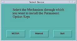
Select Permanent.
-
Select the MEDIA button and insert the Options DVD.
-
Select OK. Software options available for installation are displayed on the options screen.
-
Select options one at a time from the Available Options List and select Install to update each selection and place it on the Installed Options List.
-
Select Quit to exit the window when the process is complete.
-
Select Quit again to exit Install Options window.
-
A window pops-up displaying: “Application should be shutdown and restarted for installed/removed options to take effect.”
-
Select OK.
-
Press the button on the DVD-RAM drive on SCSI Tower to eject the option DVD.
-
Close the Service Desktop window in the upper left corner of the screen.
-
Do not remove the DVD-RAM from the SCSI Tower DVD-RAM drive.
3.11 Load Limited Access Software
-
Open a Unix Shell.
-
{ctuser@ hostname } su -
-
Password: #bigguy
-
Insert patch disc into the DVD-ROM drive on the HP Host Computer.
-
[root@ hostname ] patch_install -c
-
The patches on patch CD will be listed
Before installation of each patch, the window will wait for user's confirmation as follows:
I will install update <Patch Name> , is this ok ? [y/n]
-
Input y to install this patch or n to cancel installation of this patch.
-
After install all patches, type patch_status in the Shell window to confirm the patches are installed.
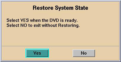
3.12 Restore System State
This procedure restores Characterization Data, Calibration Data, Protocols, etc., from your System State DVD.
-
Insert the Save System State DVD-RAM into DVD-RAM SCSI Tower drive.
-
Wait until the DVD drive is ready (i.e., until the front panel green LED is no longer lit).
-
Select: Service icon to access the CSD (Common Service Desktop).
-
Select: Utilities.
-
Select: System State.
-
Select All. This will highlight the protocols, calibration, characterization, etc.
-
Select Restore.
note:This will not affect any IP addresses (e.g., DARC Subnet) that were previously modified.
-
If applicable, select Yes when a pop-up appears to restore System State.
note:If Scan Hardware Reset question appears - answer NO. This reset is performed during FLASH Download Update.
-
Verify the CSA Protocols (reformat, Volume Viewer, etc.) were restored correctly.
-
When completed, select CANCEL.
-
Select DISMISS.
-
Close the Service Desktop window.
3.13 Save System State
|
|
New tasks are included in this SW release. These tasks will generate data that needs to be saved to the System State DVD. Follow the save and restore procedures throughout this document precisely or valuable information may be lost.
-
Insert the System State DVD-RAM into the SCSI Tower DVD RAM drive.
-
Wait until the DVD drive is ready (i.e., until the front panel green LED is no longer lit).
-
Select: Service icon to access the CSD (Common Service Desktop)..
-
Select: Utilities.
-
Select: System State.
-
Select All to select all the cals, characterizations, etc.
-
Select Save.
-
If applicable, select Yes when the following message appears: System State Media Status: Please insert a DVD into the drive and press Save again.
note:Verify that the "Save" of System State was successful. If not, correct any errors and re-save the system state. A message at the end of the Save should state: Save/Restore System State: Completed Successfully.
-
When completed, select CANCEL.
-
When completed, select Dismiss.
-
Close the Service Desktop window at the upper left corner of the screen.
3.14 Retro Recon Test
The Reconstruction (not Scan) portion of the system can be tested at this point.
-
Verify Recon is not Shutdown or Paused (in the Left Display Monitor's FSA Box). Select Recon Management then Restart Queue, if not in the Idle Mode.
-
Select Retro Recon on the left Monitor.
-
Select the Rat Gold Patient ID.
-
Select Select Series.
-
Select Confirm.
-
Verify the image(s) reconstruct and are displayed.
-
Verify the Left Monitor’s FSA Box displays successfully.
-
Remove rat gold generated images via Image Works.
-
Select Quit.
3.15 RECON Self Test
-
Select the Service Icon.
-
Select Diagnostics.
-
Select Recon Data Path.
-
Verify it is set to 1 and ALL.
-
Select Run.
-
Verify Recon Data Path tests pass.
-
Select Dismiss or close the GUI.
3.16 Flash Download
The Flash Download takes anywhere from 5-30 minutes, depending on which subsystems require updates.
-
Before running the FLASH Download Tool update, open a Unix Shell and try to ping the following, to see if there are any issues (Ctrl+C and close the shell when done pinging each one).
-
ping orp
-
ping tgp
note:If an issue exists with Flash Download, retry, then perform SYSTEM RESETS, SCAN, RUN and verify this passes, and view the log for errors.
note:Flash Download may take several times before it is successful.
-
-
Select the Service Icon.
-
Select Utilities.
-
Select FLASH Download Tool.
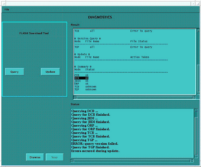
-
Select Update.
note:Ignore any TGP “unknown” messaging. This is not a problem.
-
Once the DCB/CCB/Jedi/ORP flash successfully:
Select Update.
-
Select Dismiss when then Flash Download process is a success.
3.17 Tube Usage Verification
Verify on Common Service Desktop (CSD) the number of Exams. If it does not match what was recorded earlier, then contact the OLC for directions to fix Tube Usage.
For the initial M4 Load, this step is critical to VCT Tube Warranty. 6000 Exams or 12 months.
3.18 Feature Installation
3.18.1 HIPAA
If HIPAA is turned ON, then configure it now. (Refer to HIPAA Configuration) When HIPAA configuration is complete, return to this procedure.
3.18.2 Product Network Filters (PNF)
If your customer wishes to have Product Network Filters (PNF) configured, then proceed to Configure Product Network Filters now. When PNF configuration is complete, return to this procedure.
3.18.3 AW Direct Connect
If requested by the customer, configure AW Direct Connect, now. When configuration is complete, return to this procedure.
3.19 Restart the System
3.19.1 Re-Connect Hospital Network Cable to Rear Console Bulkhead
Plug the Hospital Network (HSP) Cable into the Operator Console's rear bulkhead as shown.
3.19.2 Restarting the System
-
Select the red Shutdown Icon.
-
An attention box will appear as shown below:
Select: Restart and then the OK button to shutdown and restart the system.
-
If HIPAA Present was SET TO ON--Admin Screen:
When the system comes up the following screen will be displayed if ‘HIPAA Present’ was set to On during the Application LOAD process. The admin screen requires a password and OK:
-
Operation: Login
-
Username: root
-
Password: #bigguy
-
Select OK.
-
3.20 Tube Identification
|
|
If the tube in your system has a ’Tube ID’ board, the software automatically selects the tube identity, and sets it to ‘GE Performix Tube’. There is no action needed. For all other systems or if the software does not automatically select the tub identity, follow the procedure shown below.
Do not “double click” the Tube Certification Tool. This will cause more than one tool window to be displayed, one with message service key information not available. If this happens, close window and try again. If this happens more than once, reboot system and try again.
Figure 4. Selection of Tube Identity
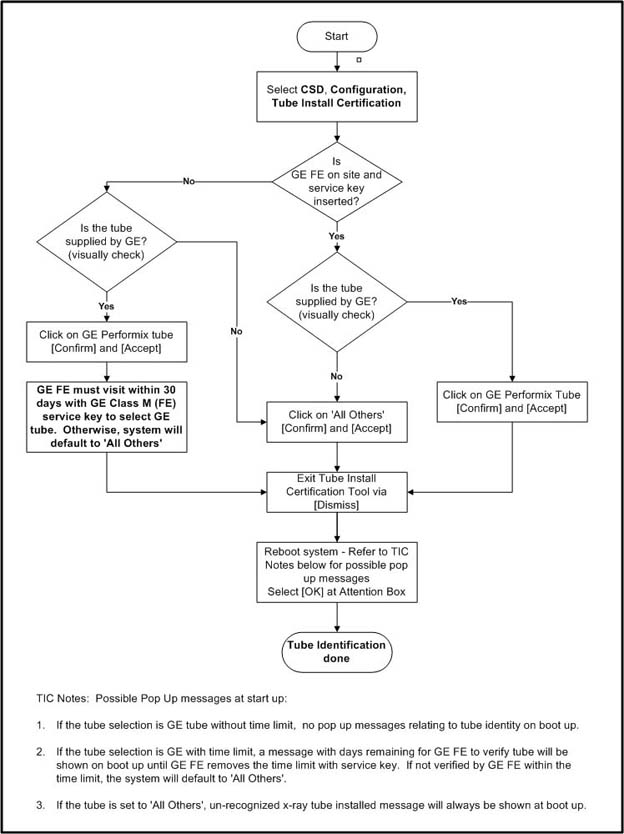
Possible Pop Up messages at start up:
-
If the tube selection is GE tube without time limit, no pop up messages relating to tube identity on boot up.
-
If the tube selection is GE with time limit, a message with days remaining for GE FE to verify tube will be shown on boot up until GE FE removes the time limit with service key. If not verified by GE FE within the time limit, the system will default to 'All Others'.
-
If the tube is set to 'All Others', unrecognized x-ray tube installed message will always be shown at boot up.
Please refer to Tube Install Certification Tool - Screens for examples of the screens displayed by the Tube Install Certification Tool.
3.21 Save System State
-
Insert the Save System State DVD into the SCSI Tower DVD-RAM drive.
-
Select Service icon.
-
Select CT button.
-
Select Utilities then System State.
-
Select All to select all the cals, characterizations, etc.
-
Select Save.
-
Select Yes.
-
When completed select Cancel then DISMISS.
-
Close the Service Desktop window in the upper left corner of the screen.
3.22 System Sanity Scanning
Load any applicable software FMIs (software patches) prior to performing system sanity scans.
-
Successfully perform a Scout scan.
-
Successfully perform a Helical scan.
-
Successfully perform an Axial scan.
-
Load Process is now complete.
3.23 Finalization
-
Remove the System State DVD-RAM from the SCSI Tower.
-
Verify VDARC Troubleshooting Cable is not connected to Scan or Display Monitors.
-
Replace the front and rear Operator Console covers.