
- SIGNA™ Hero 3.0T Service Methods
- 5852800-8EN Revision 1.0
- 00000018WIA30C89230GYZ
- id_156673461.6
- Jul 13, 2021 4:27:37 PM
Touch-n-Go (TnG) switch replacement
Prerequisites
| Required persons | Preliminary requirements | Procedure | Finalization |
|---|---|---|---|
| 1 | Not Applicable | 60 minutes | 45 minutes |
| Item | Quantity | Effectivity | Part number | Manufacturer |
|---|---|---|---|---|
| Non Magnetic Tool Set | 1 | - | - | - |
| Item | Quantity | Effectivity | Part number | Manufacturer |
|---|---|---|---|---|
| TnG Switch | 1 | - |
Refer to FRU Manual | - |
| ||||
Procedure
- Perform the following steps to remove 2 covers.
- Remove 5 screws and slide out the Motor Cover.
- Remove two rubber caps, remove 6 screws, and remove side cover.
Figure 1. Cover removal 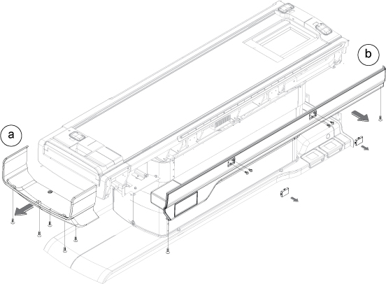
- Perform the following steps.
- Remove 11 nuts.
- Remove a connector.
- Take out TnG Switch Assy.
Figure 2. TnG removal 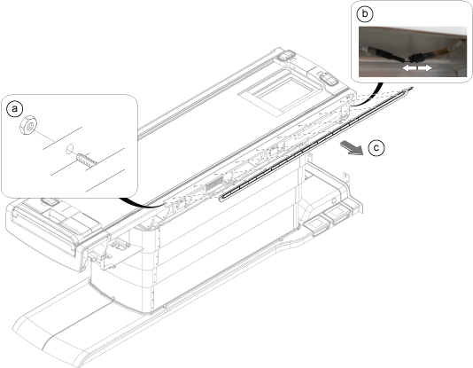
- Align the location of TnG Switch Assy and restore it per following steps.
- Insert 11 studs of TnG Switch Assy into the holes.
- Loosely screw the 11 nuts to the 11 studs.
- Adjust the TnG Switch Assy to make the TnG surface aligned with Table top FRP cover.
- Tighten the 11 nuts.
- Observe if the TnG surface is aligned with table top FRP cover or not. If not aligned, perform Step 3.b through Step 3.d until the surface is aligned, then execute next step.
- Connect the TnG cable connector.
Figure 3. TnG switch assembly location alignment 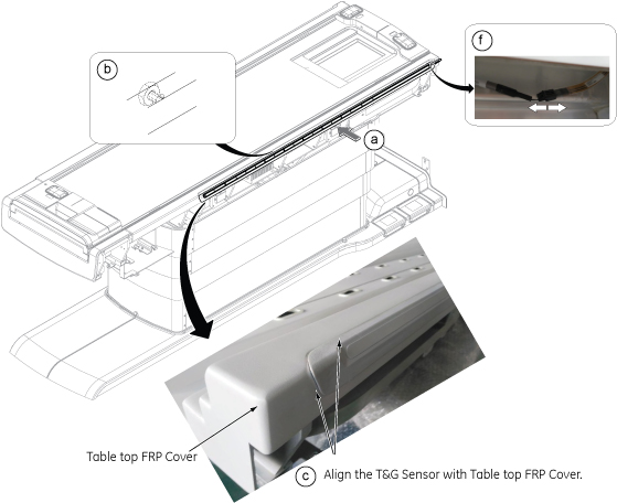
Finalization
- Turn the system power ON. Refer to Lockout / Tagout for ISC.
- Check Touch and Go function. Refer to Table Functional Check .
- Perform one test scan.