
- SIGNA™ Hero 3.0T Service Methods
- 5852800-8EN Revision 1.0
- 00000018WIA302B9280GYZ
- id_20336601.34
- Jan 26, 2022 2:38:23 AM
Installing the penetration panel for remote (off the wall) siting configuration
Installing the penetration panel
Procedure
- In the equipment room, install 36 mounting blocks and 36 screws on the RF shield wall around the wall opening.Note: The RF vendor must supply the M6 fasteners, M6 nuts, and M6 washers (36 each) to mount the penetration panel to the GE-supplied mounting blocks.
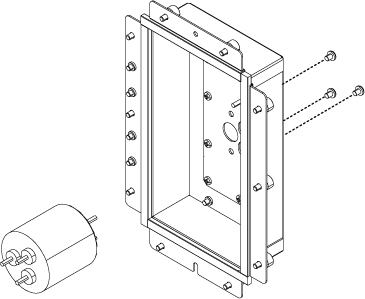
Figure 1. Penetration panel hardware 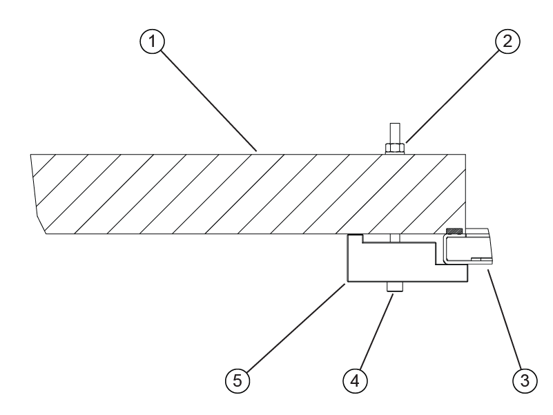
1 RF shield wall 2 Nut 3 Penetration panel 4 Screw 5 Mounting block - From the equipment room, install the penetration panel in the wall opening using the attached hanging studs. Note: Hardware for the penetration panel installation is contained in the bags attached to the penetration panel.Note: Remove the yellow plastic sheeting from the penetration panel before its installation.
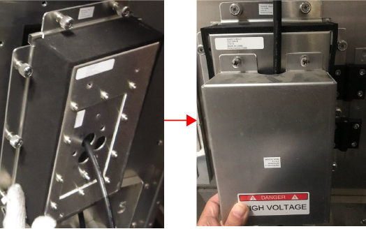
Figure 2. Remove the yellow plastic sheeting 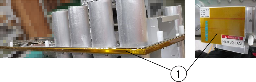
1 Yellow plastic sheeting Figure 3. Penetration Panel installation 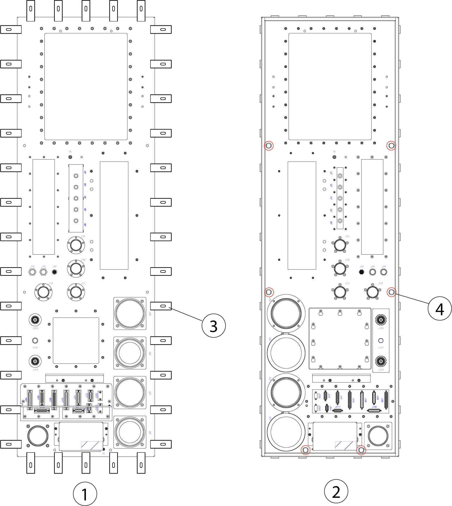
1 Equipment room 2 Scan room 3 Mounting block 4 Hanging stud
Installing the coldhead EMI filter on the penetration panel
Procedure
- Remove the coldhead EMI filter from the ICC and install the protect cover in ICC:
- Loosen 10 screws, and open the protective cover and remove the cable in equipment room.
Figure 4. E0011 and M0011 connection 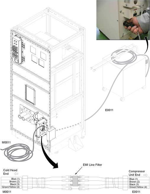
- Remove the filter by removing 3 screws on the small panel.
- Route the cable E0011 and install the protect cover on the ICC side.Note: The length of the E0011 cable along with the compressor is 16m for the normal length. If the distance is longer, the optional E0011 cable (19m) can be used for remote siting configuration.
- Loosen 10 screws, and open the protective cover and remove the cable in equipment room.
- Remove 2 screws to remove the protective cover from each side of the penetration panel as shown below.
Figure 5. Install the protect cover 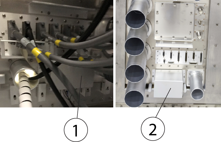
1 Protect cover in the equipment room 2 Protect cover in the scan room - Install the coldhead EMI filter to the penetration panel.
Figure 6. Install the coldhead EMI filter 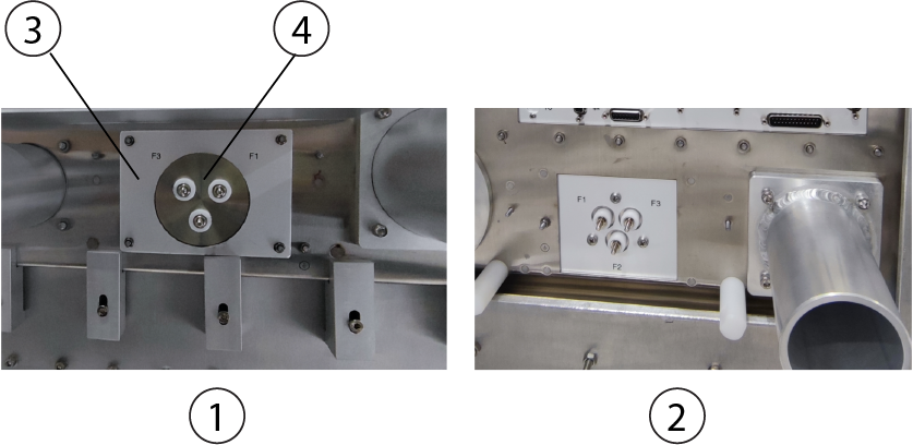
1 Equipment room side 2 Scan room side 3 Small adapter 4 EMI Filter - Connect E0011 from the compressor to the filter in the equipment room.
- Connect and secure the ground cable (yellow/green) onto the ground point. Note: Make sure the color codes on equipment room match with magnet room side.
Figure 7. Ground Point 
- Connect and secure the ground cable (yellow/green) onto the ground point.
Installing the gradient filter assembly on the penetration panel
About this task
| CAUTION | |
|---|---|
Procedure
- Remove the gradient filter covers if they are not already removed.
Figure 8. Remove the covers 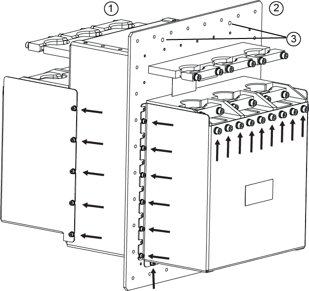
1 Scan room side 2 Equipment room side 3 Guide peg holes - Secure the gradient filter plate to the penetration panel and use the supplied 32 pcs screws (1000-M5C012-31) and 32 pcs washers [(2000-M5-10) and (2203-M5-16)].
Figure 9. Secure the gradient filter to the Penetration Panel 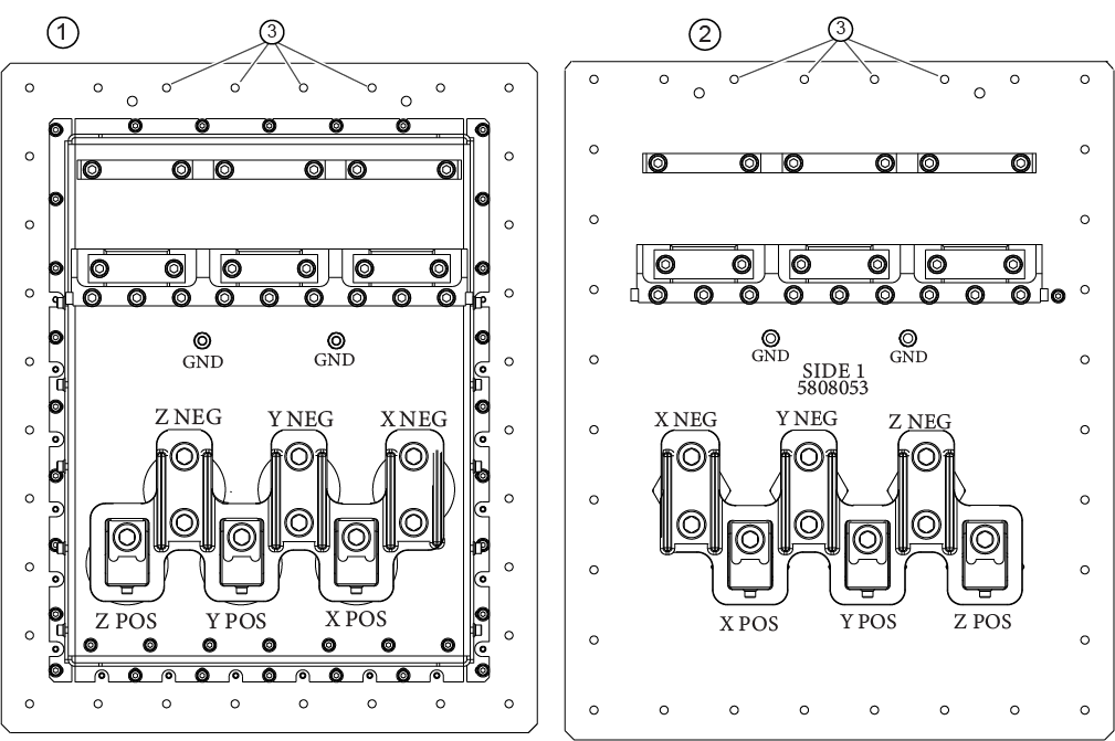
1 Scan room side, cover removed 2 Equipment room side, cover removed 3 Screw holes (32 total) - Remove the 6 ground double clamps from both the equipment room and the scan room.
Figure 10. Old ground double clamps 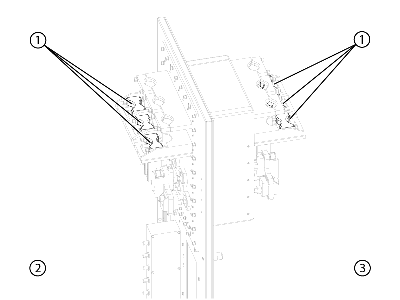
1 Old clamps 2 Equipment room 3 Scan room - Install the new clamps (5873390) in the equipment room and the scan room, do not secure the clamps until the gradient cables are installed.
Figure 11. Install the new clamps 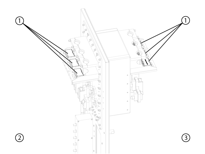
1 New clamps 2 Equipment room 3 Scan room - Install the remote cable bracket (5866655) in the equipment room and the scan room.
Figure 12. Install remote cable Bracket 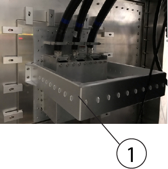
1 Remote cable bracket (5866655)
Installing the DCPS filter on the penetration panel
Procedure
Install the DCPS filter (6859100) by fixing 16 pcs screws (1007-M5C010-31) in the scan room if it has not be pre-installed on the penetration panel.
Figure 13. Install DCPS filter 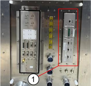
| 1 | DCPS filter (6859100) |
Installing the BNC/DB filter on the penetration panel
Procedure
- Remove 6 fiber connectors from BNC/DB filter, keep the screws and reuse them in the next step.
Figure 14. BNC/DB filter 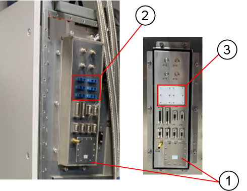
1 Thru panel assembly (5549212) 2 6 fiber connectors 3 Small blank plate Note: It is applicable for 48m IRD HDMI cable. - Install the blank plate on the ICC cabinet.
Figure 15. Install the thru panel assembly, small plate, and blank plate 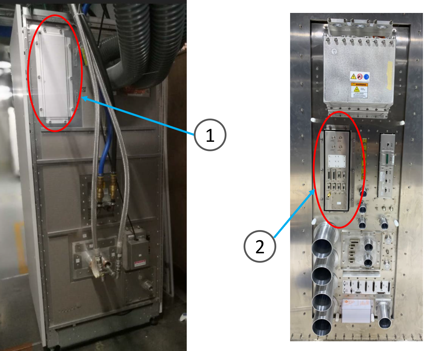
1 Blank plate 2 Thru panel assembly (5549212) and small blank plate (5874716)