
- Discovery MR750 3.0T System Service Methods
- 5690009-2EN Revision 4
- 00000018WIA3061DE20GYZ
- id_131058142.0
- Feb 22, 2021 1:47:08 AM
3.0T 32-Channel Body Array Coil Setup for MCQA Test
Prerequisites
| Required persons | Preliminary requirements | Procedure | Finalization |
|---|---|---|---|
| 1 | Not Applicable | 30 minutes | Not Applicable |
| Item | Quantity | Effectivity | Part number | Manufacturer |
|---|---|---|---|---|
| TL Unified Phantom for 3.0T | 2 | - |
5343347-2 | - |
| 3.0T Body Array Phantom Positioner Assembly (consists of upper positioner and lower positioner) | 1 | - |
5400426 | - |
About this task
The 3.0T 32-channel body array coil (PN 5391469) consists of anterior coil (PN 5391468) and posterior coil (PN 5392802). It is recommended that you perform MCQA scans using the full mode when both anterior and posterior coil are available.
This module provides setup instructions for:
The 3.0T body array coil MCQA test uses the 3.0T phantoms, which are pink.
Note:
Coils do not ship with phantoms. Phantoms come in a unified phantom set with the MR system.
Full Mode MCQA Setup
Procedure
- Place the body array lower phantom positioner on the side of
the posterior coil. Confirm that the edge of the phantom position
aligns with the edge of the table and is in contact with the posterior
coil.
Figure 1. Positioning of Posterior Coil on Table 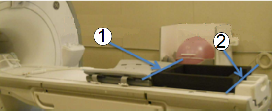
Item Description 1 Edge of coil and phantom positioner 2 Edge of phantom positioner and table - Place the lower body array phantom positioner on the posterior
coil. Center the lower phantom positioner L/R on the posterior coil.
Place the unified phantoms inside the lower positioner. Place the
upper body array phantom positioner. Make sure the side with the wider
edge foam points towards the LPCA and magnet side.
Figure 2. Unified Phantoms inside Lower Phantom Positioner 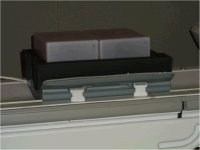
Figure 3. Upper Phantom Positioner Placed on Lower Phantom Positioner 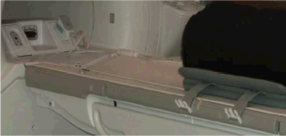
- Place the anterior coil on top of the upper phantom positioner.
Be sure the anterior is centered directly over the posterior coil.
Fasten the straps of the anterior and posterior coil. Plug the anterior
coil in connector P1 on the LPCA.
Figure 4. Phantom Positioners Centered Left-Right on Posterior Coil 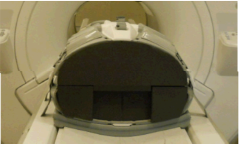
- Landmark at the center cross-hair of the anterior coil and advance
to scan.
Figure 5. Landmark Location on Anterior Coil 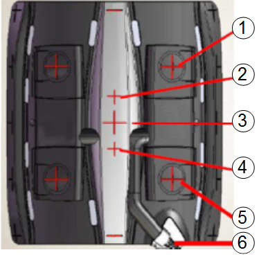
Item Description 1 Up2 2 Up3 3 Center 4 Low3 5 Low2 6 Cable Figure 6. Landmark Setup with Coil inside Bore 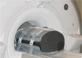
Anterior Only Mode MCQA Setup
Procedure
- Place the phantoms inside the bottom positioner. Make sure the
side with the wider edge foam points towards the LPCA and magnet side.
Figure 7. Both Phantom Positioners on Table 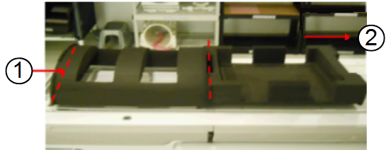
Item Description 1 Edge of upper phantom positioner aligned with edge of table 2 Direction to magnet - Landmark at the center cross-hair of the anterior coil Figure 8 and advance
to scan.
Figure 8. Landmark Location on Anterior Coil 
Posterior Only Mode MCQA Setup
Procedure
- Place the body array phantom positioner (lower) on the side
of the posterior coil. Ensure that the edge of the phantom positioner
aligns with the edge of the table and is in contact with the posterior
coil as shown.
Figure 9. Positioning Posterior Coil on Table Item Description 1 Edge of coil and phantom positioner 2 Edge of phantom positioner and table - Place the upper phantom positioner. Confirm that the side with
the wider edge foam points towards the LPCA and magnet side.
Figure 10. Unified Phantoms inside Lower Phantom Positioner Figure 11. Upper Phantom Positioner on Top of Lower Phantom Positioner - Landmark at the center of the phantom positioner. Press Advance to scan.
Figure 12. Landmark on Upper Phantom Positioner 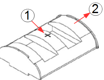
Item Description 1 Landmark spot on upper phantom positioner 2 Direction to magnet/LPCA
Finalization
Finalization
After the test is complete, remove the phantom positioners, the phantoms, and the coil. Return them to their storage area.