
- Discovery MR750 3.0T System Service Methods
- 5690009-2EN Revision 4
- 00000018WIA303A9030GYZ
- id_123749094.2
- Oct 11, 2021 3:47:43 PM
System power on
-
Confirm LOTO has been performed on the MDP.
Notice Figure 1. GE MDP 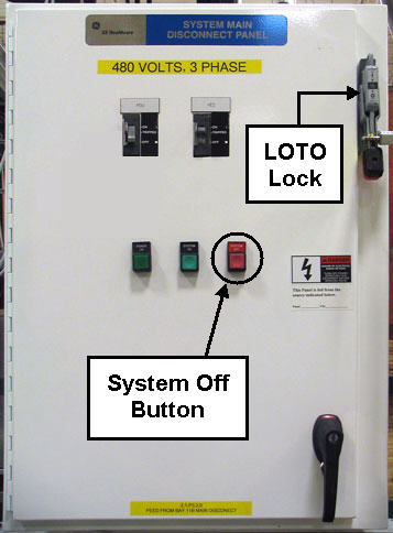
Figure 2. TEAL MDP 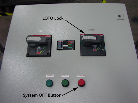
- Confirm that the MDP voltage selection is correct. (The MDP is shipped with the default voltage setting of 480 VAC).
- Confirm that the power transformer connections are properly configured.
Table 1. Power transformer connections Incoming Voltage GE Transformer Terminal TEAL Transformer Terminal 380 VAC H3 H4 400 VAC H3 H5 415 VAC H3 H5 480 VAC H4 H6 - If the power connections are not configured correctly, have the proper personnel correct the wiring connections. See Main Disconnect Panel (MDP) Service Manual for details.
Figure 3. GE MDP control power tansformer (H4 input wiring shown) 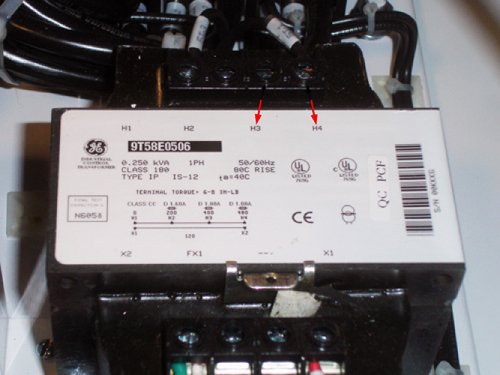
Figure 4. TEAL MDP control power transformer 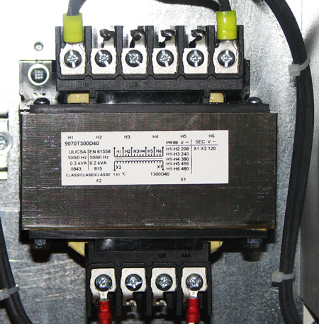
- Confirm that the power transformer connections are properly configured.
- Confirm that the Heat Exchanger Cabinet (HEC) voltage selection is correct.
Figure 5. HEC 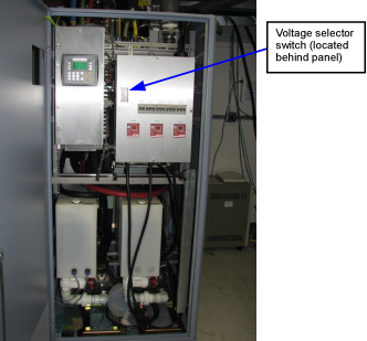
- Confirm that the switch is in the proper position.
Table 2. HEC voltage switch positions Incoming Voltage HEC Voltage Switch Position 480 VAC Up 415 VAC 400 VAC 380 VAC Down Note: Valid incoming voltages are 380 (voltage switch in the DOWN position), and 480, 415, 400 (voltage switch in the UP position). - If the switch is not in the correct position, correct the setting.
Figure 6. HEC voltage selection switch 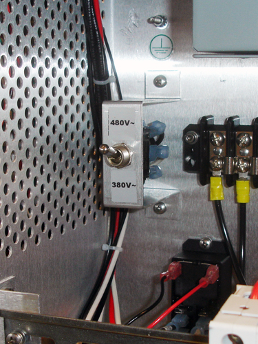
- Confirm that the switch is in the proper position.
- Confirm the incoming power wiring to the Power Distribution Unit (PDU) located in the PGR cabinet.
Figure 7. PGR cabinet 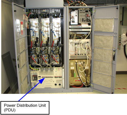
- Remove the small cover plate.
Figure 8. Pre-DVapps input voltage select cover (79 kVA PDU) 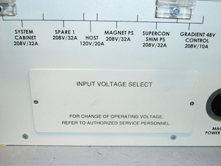
Figure 9. Input voltage select cover (73 kVA PDU) 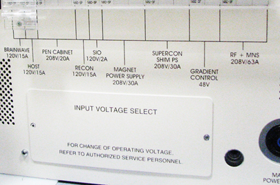
- Confirm that the three input voltage selection terminal blocks are correctly wired. If the power connections are not correctly wired, have the proper personnel correct the wiring. Verify that the connections are properly configured before proceeding. See Teal PDU Installation and Maintenance for details.
Figure 10. Input voltage selection - set at 480 VAC 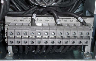
Note: The following step only applies to pre-DVapps applications. The DVapps PDU 5343114 is not adjustable. - Remove the small cover plate.
- Confirm the overload and short circuit trip settings for the PDU input circuit breaker.
- Remove the small cover plate under the main circuit breaker. Lift open the transparent plastic cover on the lower portion of the circuit breaker to access the DIP switches controlling the circuit breaker operation.
- The following illustration shows the position of the DIP switches for each input voltage selection. Verify that the switches under the letter “L” are configured correctly.
Figure 11. Circuit breaker DIP switch settings 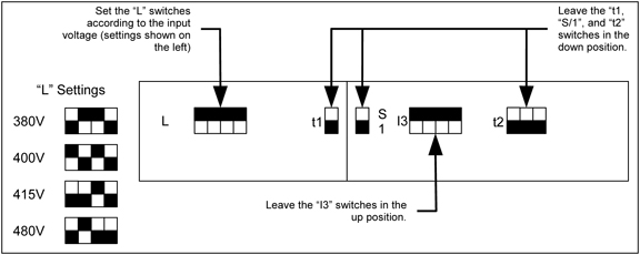 Note: In the diagram above, the black squares represent the switch positions. For example, if the black square is on the top, the switch is up.
If the DIP switches are not correctly set, have the proper personnel correct the DIP switch settings according to Teal PDU Installation and Maintenance.
- Verify that all circuit breakers on the front of the PGR cabinet PDU are in the OFF position.
- Notify field service and other installation personnel who are working at the installation site that the MDP LOTO will be removed so the MDP power can be turned on.Note:Before powering on the HEC, check all plumbing fittings and valves.
- After applying power to the pumps via the HEC, verify there are no leaks. Check the back of the XRM gradient coil hose fittings for leaks.
- The XRM cooling hoses can leak if a hose is pushed into the connector before the blue lock ring is installed. Install the blue lock ring, then push the hose into the XRM until it clicks into place, indicating that the hose connection is secure.
The blue coolant fluid can stain floors.
- Restore power (in this order) to the MDP, HEC, then PDU.
- Switch on the PDU's main input circuit breaker.
- Press the EMO RESET button on the PDU front control panel.Note: In the following step, turn on the Gradient 420V Power CB last.
- Except for the gradient cabinet power modules, switch all cabinet circuit breakers to ON and GRADIENT 420V POWER CB last. (The gradient cabinet power module circuit breakers should remain OFF until the room humidity stabilizes under 60 percent.)
- Confirm that the magnet monitor power is connected to the customer source.