Water Manifold
Prerequisites
Procedure
- Remove L Front Upper Cover and Front Lower Cover. Refer to SC Cover Removal.
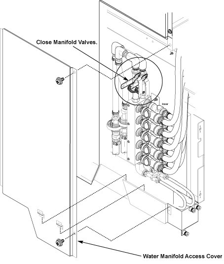
- Remove Water Manifold Access Cover by removing two screws.
- Close the Manifold Valves.
Figure 1. Water Manifold Access Cover and Manifold Valves
- notice
- Set the equipped water tray on drip for false operation prevention of sensor.
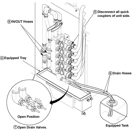
- Disconnect the all quick couplers of unit side from water manifold.
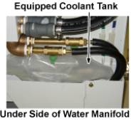
- Set the drain hoses to the equipped coolant tank.note:
The Equipped Coolant Tank is found in the drip pan of SC left side.
note:The water tray is found in SC Left shelf under cabinet monitor.
Figure 2. Location of Coolant Tank, Water tray, and Hand Pump
- Open the drain valves.
- Remove the hose clamps by removing 4 nuts and disconnect the
IN/OUT hoses from the water manifold.
Figure 3. Disconnect Hoses and Draining Setting
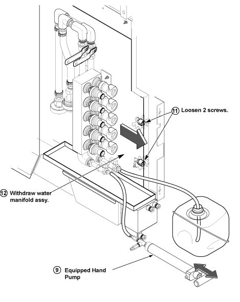
- Connect equipped hand pump to hose of one side, and push out remaining coolant.
- Disconnect connectors of leak sensor if it interferes to withdraw water manifold assy.
- Loosen 2 screws of front side of water manifold assy.
- Withdraw the water manifold assy from SC.
Figure 4. Push Out Coolant
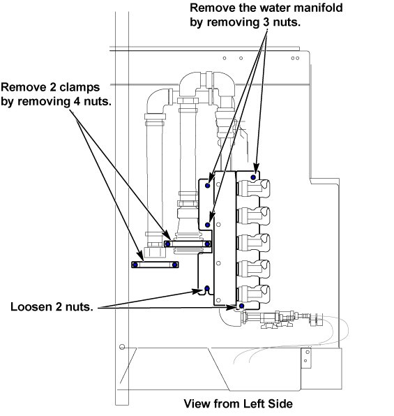
- Loosen 2 nuts of water manifold under side with 10 mm wrench.
- Remove the water manifold assy by removing 3nuts with 10 mm
wrench.
Figure 5. Water Manifold Removal
- Install the water manifold with reverse order of removal.
 |
1 Finalization
|
|
Procedure
- Restore the Power. Refer to System Cabinet PDU Main Breaker LOTO Procedure.
- Check that there is not a water leak from the water manifold.
- Perform Signal to Noise - Head Scan.