Spike Noise Check
Prerequisites
This procedure describes the check for spike noise. The following functions are a part of the check:
-
See Hardware Preparation for Spike Noise Data Collection for “Hardware Preparation for Spike Noise Data Collection.”
-
See Spike Noise Scan Preparation for “Spike Noise Scan Preparation.”
-
See Sample Noise Data Collection and Analysis for “Sample Noise Data Collection and Analysis.”
1 Hardware Preparation for Spike Noise Data Collection
Procedure
- Connect the oscilloscope power plug to the service outlet or power strip inside the System cabinet to prevent ground loops that may cause higher floor noise.
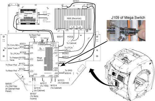
- Connect a BNC cable to J109 of the Mega
Switch. Connect the other end of this cable to an open port on the
2nd Pen Panel.note:
An extra length of BNC-to-BNC cable may be needed to reach the PEN panel.
Figure 1. J109, Mega SW Connection
- With a coaxial cable connect the 2nd PEN panel port to channel 1 (CH1) on the oscilloscope (o-scope).
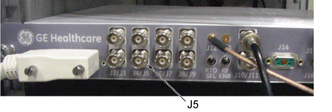
- Connect another coaxial cable to J5 on
the Exciter panel. Connect the other end of the coaxial cable to channel
2 (CH2) on the o-scope.
Figure 2. J5, Exciter
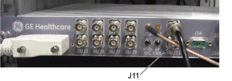
- Connect another coaxial cable to J11 on
the Exciter panel. Connect the other end of the coaxial cable to the Trigger Input on the o-scope.
Figure 3. J11, Exciter
- Set up the oscilloscope as follows:
- Channel 1 - 100 mV/div, 1 mW input, AC coupled, 1 meg ohm impedance.
- Channel 2 - 5 V/div, 1 mW input, DC coupled, 1 meg ohm impedance.
- Time Base - 2 msec/div.
- Trigger - auto, external.
2 Spike Noise Scan Preparation
Procedure
- At the operator workspace, select the Scan icon on the desktop control panel.
- If necessary, exit out of any previous exams by selecting End Exam.
- Click New Pt and enter the following:
- Name: spike noise
- ID: geservice
- Weight (lb.): 111
- Remove all phantoms from the patient table. This is an empty bore test.
- Place the head coil without a phantom on the cradle. Landmark on the center of the head coil. At the keypad on the front magnet enclosure, press LANDMARK and MOVE TO SCAN.
- Click Start Exam and then press Move to Scan.note:
Use Series 2-8 per later procedure steps.
3 Sample Noise Data Collection and Analysis
Procedure
- At the Operator Workspace, click Manual Prescan and set R1 = 11, R2 = 15, TG =0 and select Scan TR.
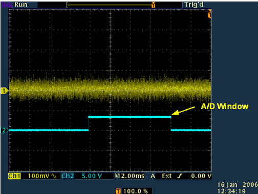
- Go to the oscilloscope and adjust the scope trigger to display
one cycle of the A/D window on the scope channel 2.
Figure 4. Oscilloscope Display For A/D Window
- Press the PAUSE SCAN button on the console
keyboard. Press the FAN button on the magnet
enclosure to turn off the patient comfort fan (the fan turns on automatically
with scan software).note:
Ignore the first 30 seconds of data.
- The Mulit-Generational Data acquisition/Radio Frequency (MGD/RF) are now in the receive mode and any noise can be observed at the Mega Switch Spike Detect port. The scope must be in auto trigger mode.
- Put the scope in continuous acquisition mode. The method for doing this varies with the type of scope. Clear the oscilloscope display and ensure the trigger is in the auto position.
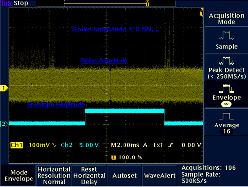
- Observe the scope display for about two minutes. The noise envelope
(channel 1) is typically 200 mV p–p. Check that there are no spikes
>0.5 Nenv (where Nenv is the noise envelope peak to peak value) above the noise envelope.
Figure 5. Spike Noise Scope Waveform (Paused Prescan)
 note:
note:Ideally, there should be no spikes beyond the envelope. Any spikes present indicate that a connection is loose, or a component is bad (e.g., intermittent connection of power cable to a shield cooler cold head, or copper fingers on exam room door are damaged). Noise spikes that are greater than the spike spec create images with corduroy-like artifacts. Noise spikes that are presently less than the spike spec get worse over time.
note:If there are no spikes present and there I sdoubt whether the setup is working, simulate an RF leak by opening the exam room door, or by turning the room lights on or off if the site is RF quiet. Clear the oscilloscope display and observe the new waveform on the display. Noise spikes should display beyond the waveform envelope. Do not forget to close the exam room door when finished.
- Press the FAN button on the magnet enclosure to turn on the patient comfort fan. Clear the oscilloscope display and ensure that the trigger is in the Auto position. Observe the oscilloscope display for about two minutes. The noise envelope (channel 1) should remain as described in Step 6 above.
- Clear the oscilloscope display and change the trigger from Auto to Normal.
- Press the FAN button on the magnet enclosure to turn off the patient comfort fan.
- Press the START SCAN button on the console keyboard to resume pre-scan. Click on Scan T/R.
- Observe the scope display after two minutes. The noise envelope
(channel 1) should be approximately 200 mV. Check that there are no
spikes >0.5 Nenv (where Nenv is the noise envelope peak-to-peak value) above the noise envelope
in the region of interest (except for maybe a beginning and ending
transition spike). See Figure 5.note:
The Region of Interest extends beyond when the observed Data In Window signal is high because the Data In Window position varies with Excitation Time (TE). The Transition Spike (not always present) occurs when the RF subsystem transitions from transmit to receive frequency; it occurs ~1 msec prior to the Data In Window. (The frequency transition point can be confirmed by viewing the DDS OUT signal on the Exciter Board.)
note:If the spike noise appears only during pre-scan, the problem is more likely to be a loose connector, freely hanging cables near the magnet, poorly soldered components, or coil mounting hardware. Investigate anything that is subject to vibration from gradient activity.
- Click Done.
- Click New Series. Set up scan prescription for series #2 scan per notes and Table 4, then repeat steps Sample Noise Data Collection and Analysis.
- Repeat the previous step until all head pre-scans (series #1 through #4) are complete.
4 Finalization
Procedure
- When you’re done with the loopback testing then restore the cabling to the default clinical state.
- Perform a Check Scan to check the system operation.