Patient Table Casters
Prerequisites
Overview
There are two types of casters on the patient transport: a straight-line tracking (steering) caster that is mounted on the right front side of the patient transport, or three lock type casters (see Illustration L2670A).
Procedure
- Unlock patient transport, and move from exam room.
- Prepare block of wood to support table when casters are replaced.
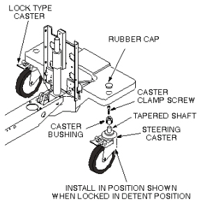
- Remove rubber cap from the caster to be replaced (see Figure 1).
Figure 1. CASTER WHEEL ASSEMBLY
- Remove caster clamp screw (center screw) from the caster to be replaced.
- Repeat steps Step 3 and Step 4 on any one of the other casters, because two caster clamp screws are required to force the tapered caster shaft out of the caster bushing on the defective caster.
- Return to the caster to be replaced. Thread the two caster clamp screws in the vacant caster release screw holes of the caster bushing. Force the tapered caster shaft out of the caster bushing by tightening two caster clamp screws, equally, a little at a time, until caster taper fit breaks loose and caster falls off.
- Be sure that bushing is not bell-mouthed at bottom. If bushing
is damaged, remove by turning out of the bottom of the casting using
a 3/4-inch (19 mm) socket.note:
If new bushing is required, apply synthetic lubricating grease to inside taper and threads of bushing before installation.
- Using synthetic lubricating grease, lubricate tapered stem of caster and threads of caster clamp screw.
- Install new caster into bushing. Straight line tracking (steering)
caster should be installed so that it is oriented in position shown
when locked in detent position (see Figure 2).
Figure 2. CASTER WHEEL ASSEMBLY
- Install caster clamp screw and tighten.
- Remove support wood blocks.
- Perform procedure for Checking Caster Height Adjustment in Leveling Patient Transport Procedure.note:
Equipment damage possibility. Caster adjustments must be done according to Leveling Patient Transport Procedure. Mis-adjustments leave caster bushing vulnerable to damage, which can result in injury to patient and/or persons near patient transport.
1 Finalization
Procedure
- Verify that Caster can be locked.
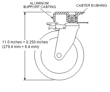
- Measure the height from floor to top of aluminum support casting. Verify that the height is within be 11.0 inches ± 0.250 inches (280 mm ± 6.35 mm).
Figure 3. Height from floor to top of aluminum support casting
- Dock the Table and move the Table to the up limit position. Verify that the Table and Bridge are horizontally aligned and there is no height difference of Table and Bridge at right and left position.
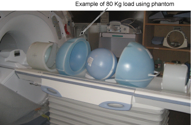
- Place the 80Kg Load evenly on the Cradle. If using the phantom, refer to the following illustration.
Figure 4. 80 Kg load
- Verify that Table moves up and down fully and smoothly using the pedal of Table.
- Verify that Table moves up and down fully and smoothly using the pedal of Dock.
- Verify that Cradle moves in and out fully and smoothly.
- Verify that all of the parts and the screws are installed.
- Verify that there is no wound or dirt on the Table, Cradle, Pad, and Patient Strap.