Leveling Patient Transport
Prerequisites
The Patient Transport is levelled by adjusting caster height; however, caster height must also be checked for uniform loading.
1 Checking Levelness of Patient Transport
Procedure
- Dock the Patient Transport. If docking mechanism is not properly adjusted yet, position the Patient Transport in the location it will be in when it is docked.
- Lock the caster brakes.
- With table top in fully raised position, check Patient Transport
for levelness, both front-to-back and left-to-right. This should be
checked at the table top level, not at the table base, since table
top alignment is the critical factor. See Figure 1.
Figure 1. CHECKING LEVELNESS OF PATIENT TRANSPORT
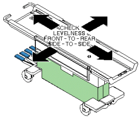
- Check that all casters are sharing the load approximately equally by applying a small lifting force at each corner of the table and seeing if the caster easily lifts off the floor.
- 5. If one caster or two diagonally mounted casters seem to not be loaded as much as the other casters, they will require adjustment.
2 Checking Caster Height Adjustment
Procedure
- To help keep track of measurement data, temporarily label each caster as 1, 2, 3, and 4. Suggestion: label "steering" caster (green colored locking tab) as 1, and proceed labeling in a clockwise direction.
- At each of the four caster wheel assemblies, measure the height
from floor to top of aluminum support casting (see Figure 2,
measurement A). Record this measurement in Table 4,
in MEASUREMENT A column labeled 1ST HEIGHT. This height should be
11.0 inches +/- 0.250 inches (279.4 mm +/- 6.4 mm). If 1ST HEIGHT
MEASUREMENT A is not within tolerance, calculate amount by which
it is out of tolerance ("+" if caster height is too small; "-" if
height is too large) and record this value in 1ST DELTA column under
MEASUREMENT A.
Figure 2. CASTER MEASUREMENTS
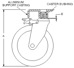 note:
note:Tolerance for MEASUREMENT A: 11.0 +/- 0.250 inch
Tolerance for MEASUREMENT B: <0.250 inch
- At each of the four caster wheel assemblies, measure the gap between bottom of caster bushing and base of caster shaft (see Figure 2, measurement B). Record this measurement in Table 2, in MEASUREMENT B column labeled GAP. The acceptable measurement for this gap is less than 0.250 inches (6.4 mm). If gap is not within tolerance, calculate amount by which it is out of tolerance ("+" if gap is too small; "-" if gap is too large, and record this value in DELTA column under MEASUREMENT B.
3 Caster Mounting Hardware Design Description
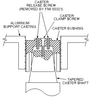
When the caster bushing can turn freely inside the aluminum support casting, the bushing provides a means of adjusting caster height. The bushing is slotted and has a tapered hole to accept the tapered caster shaft. See Figure 3. When the caster clamp screw is inserted through the bushing and tightened securely into the caster shaft, the shaft is drawn up into the bushing, causing the bushing to spread tightly against the aluminum support casting threads, preventing the bushing from turning and changing the height adjustment. To adjust caster height, the clamp screw is backed out of the caster shaft and the caster release screws (or 2 caster clamp screws after FMI 60321 has been performed) are turned into the caster bushing. The release screws push the caster shaft out of its tapered fit in the caster bushing, leaving the bushing loose enough to turn and provide caster height adjustment. After adjustment, the release screws must be backed out to prevent contact with the caster shaft. Then the clamp screw can be adequately tightened, securing the caster shaft and immobilizing the bushing. There are two conditions that could cause the caster assembly to come loose and possibly fall off the Patient Transport. These two conditions, their causes, and solutions are described below.
Procedure
- Problem Conditions and Causes:
- The tapered caster shaft can become loose and back out of the caster bushing. This condition can occur if the caster clamp screw has not been adequately tightened or is missing altogether. This condition can also be caused if the caster release screws were left in too far, before tightening the caster clamp screw, while adjusting caster height. The screws would be pushing against the caster shaft, preventing the shaft from seating securely into the bushing.
- The caster bushing can back out (partially or completely) of its threaded hole in the support casting. If the tapered caster shaft becomes loose (as described in condition 1), or if the caster bushing has been improperly positioned during caster height adjustment (correct bushing positioning will be detailed in Patient Transport Leveling Procedure- Patient Transport Leveling Procedure) the bushing can back out of the aluminum support casting.
Figure 3. CASTER MOUNTING CONSTRUCTION
- Solutions:
- To avoid the condition caused by leaving the caster release screws in too far, FMI 60321 eliminates the caster release screws from the caster assembly hardware (also currently being removed from all forward production Patient Transports). When it becomes necessary to force the tapered caster shaft out of the caster bushing during an adjustment procedure, two caster clamp screws will be used in the vacant caster release screw holes. One of the caster clamp screws will come from the caster being adjusted, and one will be borrowed from another caster assembly.
- A 50 in-lb torque requirement for the caster clamp screw. This torque on the caster clamp screw will result in sufficient tightness of the caster bushing inside the aluminum support casting to prevent the bushing from backing out when the caster assembly swivels. This torque requirement is currently in effect for all forward production Patient Transports and is required for FMI 60321.
4 Patient Transport Leveling Procedure
Procedure
 warning
- The torque wrench and socket driver cannot be brought into magnet room. Undock Patient Transport and move it out of magnet room.
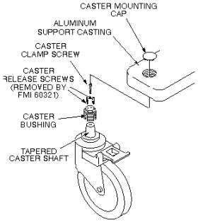
- On first caster to be adjusted, remove caster mounting cap by
prying it off with a small screwdriver. See Figure 4.
Figure 4. CASTER WHEEL ASSEMBLY
 note:
note:Adjustments which exceed tolerances given in the steps below leave caster bushing vulnerable to damage, which can result in injury to patient and/or persons near Patient Transport.
- For each caster within tolerance, as determined in Table 4 proceed
to Step 14 of this section. For each caster out of tolerance
(i.e. has a 1ST DELTA entry in Table 4)
adjust caster height by continuing with Step 4.note:
This procedure assumes FMI 60321, Signa Lightweight Patient Transport Caster Height Adjustment has been performed which removes the caster release screws from the caster assembly hardware. If FMI 60321 has not been performed, the caster release screws will still be in the screw holes.
- On first caster to be adjusted, remove caster clamp screw (cap screw) from its hole, and thread the screw into one of the empty caster release screw holes. Turn caster clamp screw in finger tight only.
- Go to another caster assembly and remove the caster clamp screw. Bring caster clamp screw back to caster being adjusted.
- At caster being adjusted, turn second caster clamp screw into the other empty caster release screw hole, finger tight only.
- Alternately screw in caster clamp screws one turn at a time until caster shaft is loose as possible in caster bushing.
- Using a means of leverage, slightly prop up aluminum support casting at caster being adjusted only enough to take Patient Transport weight off caster wheel. This will disengage caster shaft from caster bushing and prevent excessive wear on threads during adjustment.
- Remove both caster clamp screws from the two caster release screw holes.
- Adjust caster height an amount equal to the value recorded in 1ST DELTA column of MEASUREMENT A or MEASUREMENT B, whichever pertains, in Table 4. While holding caster wheel, use a 19 mm socket to turn caster bushing counter-clockwise to raise table corner (for "+" DELTA), or clockwise to lower table corner (for "-" DELTA). Each complete revolution of caster bushing raises or lowers caster 0.083 inches (2.1 mm).
- Remove prop from under aluminum support casting.
- Return borrowed caster clamp screw to its original caster assembly.
- At caster being adjusted, insert remaining caster clamp screw into caster clamp screw hole.
- Using the Torque Wrench (46-194427P255) and Socket Driver (46-307811P1), torque caster clamp screw to 50 inch-pounds. If necessary, refer to operating instructions supplied with the torque wrench.
- Verify that caster shaft is seated well into caster bushing and gap B is still within tolerance defined in Table 4.
- Move Patient Transport back into magnet room, and dock to the magnet.
- For each caster, re-measure height A and record its value in Table 4, in MEASUREMENT A column labeled 2ND HEIGHT. If this 2ND value of A is out of tolerance, calculate amount by which it is out of tolerance, and record this amount in 2ND DELTA column under MEASUREMENT A.
- For each caster height still out of tolerance, adjust height as determined by value of 2ND DELTA in Table 4, by performing procedure beginning with Step 4 of this section.
- When all caster height measurements are within tolerance, replace all caster mounting caps.
Finalization
No finalization steps.