PS for Driver Module Lite
Prerequisites
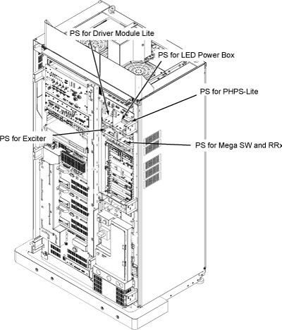
Location of each Power Supply is as following illustration
Figure 1. Location of Power Supply
Procedure
- Remove Front Cover. Refer to SC Cover Removal
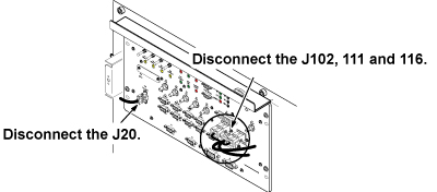
- Disconnect J20, 102, 111 and 116 connectors from front panel
of Driver Module Lite.
Figure 2. Cable Removal from Driver Module Lite
 note:
note:PS connectors are designed to be uniquely connected to the other end to avoid the mis-connection except Receiver and Exciter cable connectors.
- Disconnect the connectors which are routed from PS for Driver Module Lite. If necessary, cut the tie wraps.
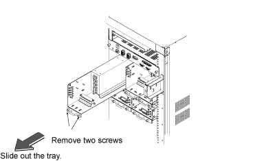
- Loosen 2 screws which are tightening power supply and chassis.

- notice
- Remove PS for Driver Module Lite from the System Cabinet.
Figure 3. Driver Module Lite power supply
- Restore the new Driver Module Lite power supply by the reverse order.
1 Finalization
Procedure
- Restore the Power. Refer to System Cabinet PDU Main Breaker LOTO Procedure.
- Run one head or body scan.