PA COIL COAXIAL AND DC CABLE
Prerequisites
Procedure
- Turn the system power OFF. Refer to .
- Remove the FRP Covers of the Table.
- Remove the scissor covers from the table. SCISSOR COVER
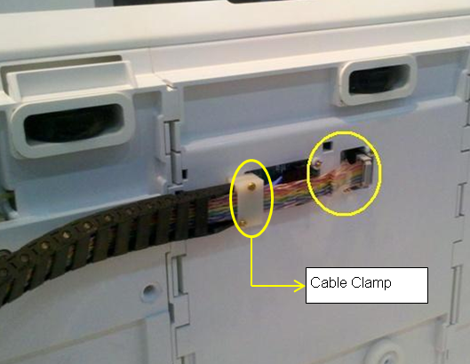
- Remove PA coil from back of table and the screws set in cable
clamps.
Figure 1. Remove PA Coil and cable clamp
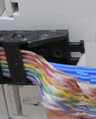
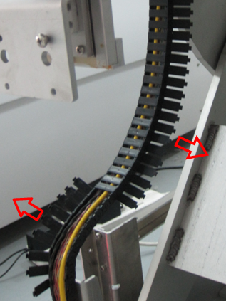
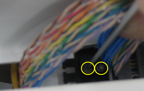
- Remove the screws underneath the cable clamp
Figure 2. Remove screws under the cable clamp
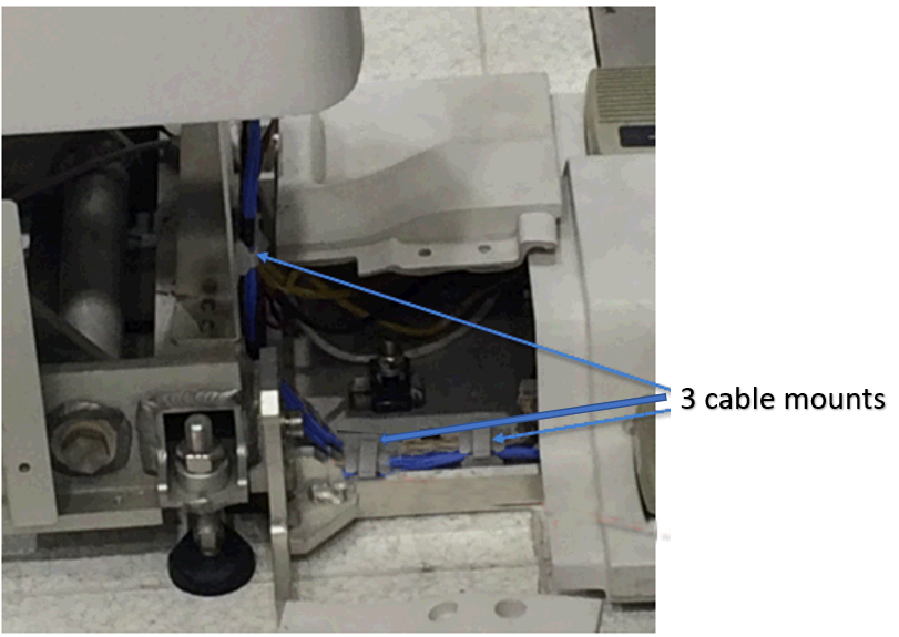
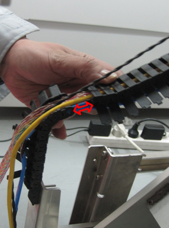
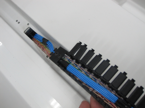
- Snap open the 3 cables clamps.
Figure 3. Cable clamps
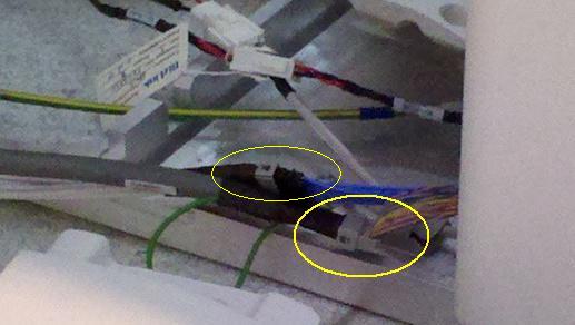
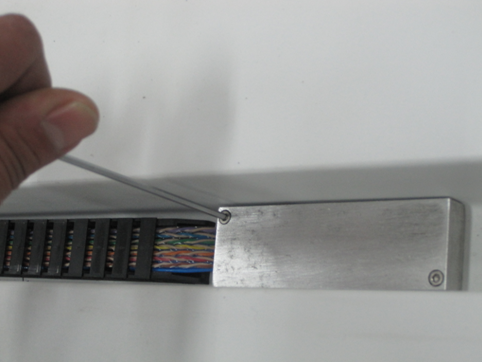
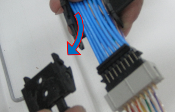
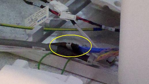
- Disconnect the Control Board Cable-2 (TEB Cable) Assembly to
the connector box.
Figure 4. Disconnect the Control Board Cable
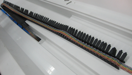
- Snap open cable track buckles.
Figure 5. Snap open cable track buckles
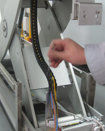
Figure 6. Open track buckles toward the direction that the tracks bulges
- Open the track at the end link
Figure 7. Open the track at the end link
- Remove the Support Block from the table.
Figure 8. Removal of Support Block
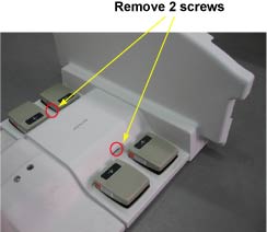
- Remove the 2 screws on the track under the cable
Figure 9. Removal of 2 screws
- Remove the track buckles on the other side of cable
Figure 10. Removal of cable buckles under the table
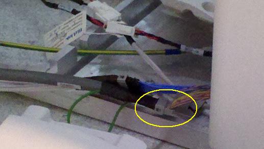
- Remove the clamp on the end of buckle, Now the control board
cable assembly is free to remove from table.
Figure 11. Remove the clamp from the buckle
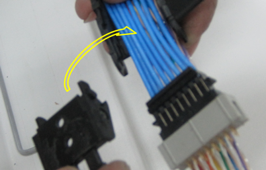
- Place the new control board cable assembly on the open cable
track to the total length.
Figure 12. Place the new control board cable
- Ensure proper projection length is given for the connection.
Figure 13. Ensure proper projection length
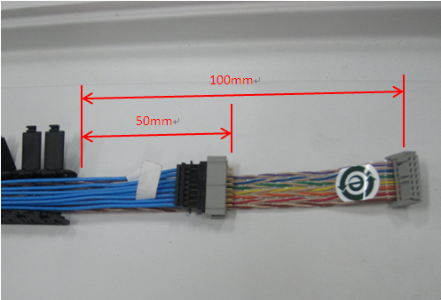 note: Please ensure blue cable is placed on top of the colored cable.
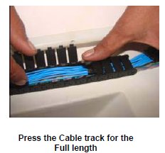
 - Press the Cable Track keeping the cable inside the Track. See Figure 14
Figure 14. Connect the Shorter length end of the cable
- Fix the clamp back into the cable buckle.
Figure 15. Fix the clamp back into cable buckle
- Route the cables in the table and wind the spiral tube around
all Assemblies.
Figure 16. Route the cables
- Connect the Control Board Cable (TEB Cable) Assembly to the
connector box.
Figure 17. Control Board Cable
- Connect the Control Board Cable-2 (TEB Cable) Assembly to the
connector box.
Figure 18. Control Board Cable–2
- Restore Cradle Assy.
- Fix the scissor covers to the table. Refer to SCISSOR COVERS.
- Move the Fixed Table and install to Dock Frame.
- Connect the Cables to the MR Gantry.
- Fix the FRP Covers of the Table.
Finalization
- Turn the system Power ON. refer to Lockout / Tagout for System Cabinet PDU Main Breaker.
- Perform Express Coil MCQA Test/