Motor On Switch Actuation Adjustment
Prerequisites
The Dock Motor Speed Procedure is required as part of set-up and calibration. Procedures for opening magnet enclosure covers and adjusting patient dock hardware (Dock Motor Gear Assembly Adjustments) are provided in case related Dock problems arise. The Motor On actuation switch in the dock assembly should be adjusted so it is activated when the Table Up foot pedal is pressed approximately 3/4 of its total length of travel. This is factory adjusted; however, it is possible to adjust the position of the Motor On switch in the field to maintain the proper actuation level.
Procedure
- Remove power to dock. Refer to the appropriate Lockout / Tagout for System Cabinet PDU Main Breaker.
- Undock patient transport.
- Remove dock assembly from dock support by removing capscrews,
lock washers, and clamps (Figure 1).
Figure 1. DOCK ASSEMBLY R/R
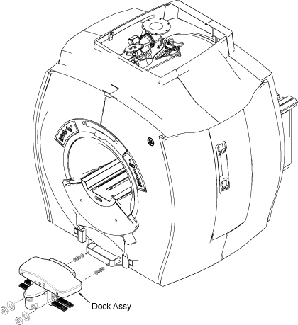
- Slide dock assembly away from magnet enclosure to gain access to cable connections.
- Remove small trim plate on front enclosure skirt, just above cutout to access dock motor power cable and Up Limit switch cable connections (Figure 1).
- Disconnect all cables from Dock Assy.
 warning
- Slide dock assembly out of scan room, observing danger precautions above.
- Remove four mounting bolts from main dock cover (Figure 2).
Figure 2. DOCK COVER REMOVAL
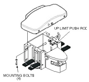
- Slide main dock cover forward until Up Limit switch push rod just clears main dock cover holes (Figure 2).
- Remove front cover by removing two nuts securing front cover
to dock (Figure 3).
Figure 3. MOTOR ON SWITCH ADJUSTMENT
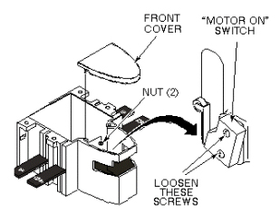
- Loosen two mounting screws securing Motor On switch to side of dock assembly (Figure 3 above).
- Adjust Motor On switch position so it is activated (clicks) when the Table Up foot pedal is pressed approximately 3/4 of its total length of travel.
- After adjustment is complete, tighten two mounting screws.
- Reinstall front cover by attaching two mounting nuts.
- Carefully position main dock cover so that Up Limit switch push rod is aligned with upper hole in main dock cover.
- Replace main dock cover by securing four mounting bolts (Figure 2).
- warning
- Slide dock assembly into scan room, observing danger precautions noted above.
- Connect cables.
- Attach small trim plate on front enclosure skirt, just above cutout (Figure 1).
- Install dock assembly to magnet enclosure with attaching hardware.
- Restore Power
- Dock patient transport.
- Ensure that dock Motor On switch operates properly when Table Up pedal is pressed.
 |
|
Finalization
No finalization steps.