LCC Dock Replacement
Prerequisites
Procedure for replacement of the following dock components.
-
The dock limit switch board.
-
The dock gear-motor and clutch assembly.
1 Removal of Dock
Procedure
 danger
- Perform Lock Out Tag Out. Refer to Lockout / Tagout for System Cabinet PDU Main Breaker .
- Undock the patient table and remove it from the scan room.
- Disconnect the two cables that are attached to the Dock. These should be the runs going to the Dock Assembly (MG2 A29) and the Dock Limit Switch (MG2 A31).
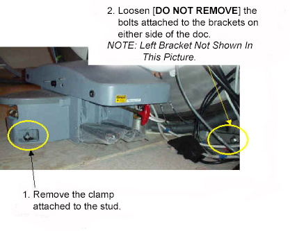
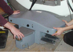
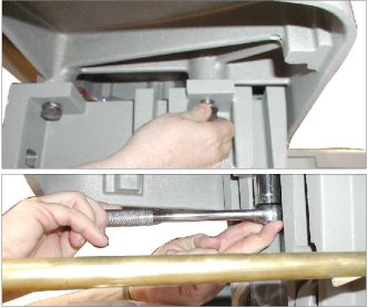
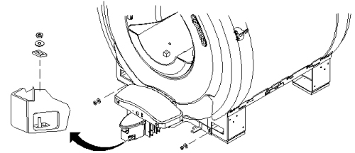
- Loosen the bolts attaching the dock assembly at the front and
at the right and left brackets. See below.
Figure 1. Loosen Dock Attachment Bolts
- warning
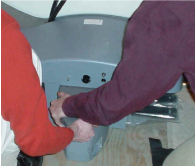
- Applying pressure to the top of the dock, completely remove
all dock attachment bolts. See Figure 2.
Figure 2. Apply Pressure To Dock And Remove Attachment Bolts
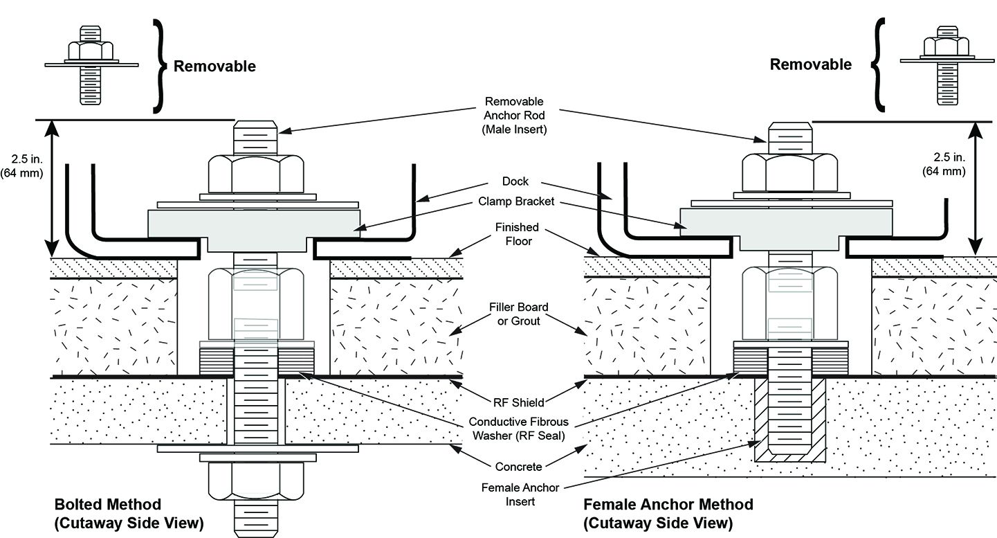
- Clear the anchor stud out of the path of the dock assembly.
There are two possibilities for how this may be done:
- If the site has followed the pre-installation manual, then it should be possible to remove the top portion of the stud so that the dock may remain flush with floor during removal. This is the preferred method.
- If the site has an anchor stud that protrudes vertically from
the floor and cannot be removed, a non-conformance MUST be raised
with the customer and the anchor must be fixed to comply with the
Pre-Installation Manual prior to any future servicing of the dock.
To complete the task this time, follow these steps:
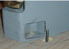
-
Measure the height of the anchor stud as indicated in the illustration below. If the height exceeds 2 inches (5 cm), the magnet MUST be ramped down prior to removing or installing the Dock as there is significant risk of the magnet attracting the Dock if it needs to be raised more than 2 inches (5 cm).
Figure 3. Measure the Height of the Anchor Stud
-
Use two people to pull the dock away from the magnet until the stud in the front is hitting the inner frame. See Figure 4.
-
Use two people to lift the dock JUST ENOUGH to clear the top of the stud in the floor. Pull the dock away from the magnet as far as possible. See Figure 5.
-
Place dock back on the floor immediately to the side of the anchor stud .
Figure 4. Lift the Dock Just Enough to Clear the Stud in the Floor
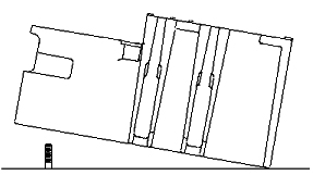
Figure 5. Place Dock Down to the Left of the Stud in the Floor
-
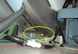
- When the distance between the dock and the magnet is at least equivalent to the distance between the magnet and where the foot of the patient table would normally be located, both field engineers may slowly lift the dock from the floor and exit the room.
- With two field engineers, one holding each side of the dock, slide the dock away from the magnet front to where the foot of the patient table would normally be located.
- When a safe distance away from the magnetic field (at least as far as the foot end of the patient table), two field engineers may slowly lift the dock from the floor and exit the room.
Figure 6. Watch for Interference Between the Bracket and the Magnet
2 Replacement of Dock Limit Switch
Procedure
- The Dock Limit Switch should only be removed AFTER following the procedure above (Removal of Dock) for Removal of Dock.
- To remove the Dock Control Assembly, see Figure 7.
Figure 7. Removal Of The Dock Control Assembly
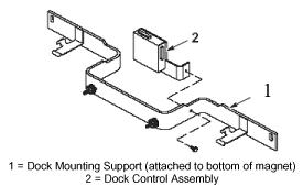
- Once the Dock Control Assembly has been detached from the dock mounting support, perform the remainder of this replacement procedure outside of the magnet room.
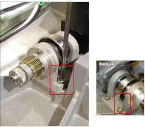
- To access the circuit board internal to the Dock Control Assembly,
see Figure 8.
Figure 8. Removal And Replacement Of Dock Limit Switch Board
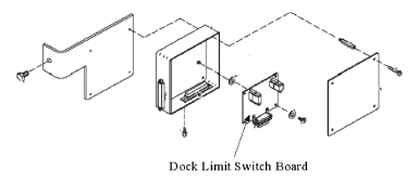
- Replace the Dock Limit Switch Board as shown in Figure 8.
- Re-assemble the Dock Control Assembly as shown in Figure 7.
- warning
- Follow the instructions in Installation of Dock to install the dock in the magnet room.
3 Replacement of Gear Motor and Clutch Assembly
Procedure
- warning
- The Motor and Clutch Assembly should only be removed AFTER completing the procedure for Removal of Dock, refer to Removal of Dock.
- Remove the upper cover of the dock by un-bolting the four hexbolts.
See Figure 9.
Figure 9. Remove Four Hexbolts From Under Dock Cover
- Slightly lift the cover and disconnect all electrical connections between the cover and the base of the dock assembly. The connections will be the ground connection for the motor and the harness for the dock motor.
- Remove the dock cover from the base.
- Disconnect the motor's ground lug from the cover. See Figure 10.
Figure 10. Motor Ground Lug Removal

- Remove the four mounting screws for the motor. See Figure 11.
Figure 11. Remove Motor Mounting Screws
- Remove existing motor.
- Install replacement motor.
- Attach motor by replacing the four mounting screws for the motor. SeeFigure 11 for location of the screws.
- Attach the motor's ground lug to the cover. See Figure 10.
- Replace the dock cover on the base.
- Reconnect all electrical connections between the cover and the base of the dock assembly. The connections are the ground connection for the motor and the harness for the dock motor.
- Replace the upper cover of the dock and secure by replacing the four hexbolts. See Figure 9.
4 Installation of Dock
Procedure
- warning
- With two field engineers, one holding each side of the dock, enter the magnet room and place the dock on the floor where the foot of the patient table would normally be located.
- With two field engineers, one applying vertical downward pressure to each side of the dock, slide the dock toward the magnet front.
- Position the dock to clear the floor stud. There are two possibilities
of how this may be done:
- If the site has followed the pre-installation manual, then when reinstalling the dock it should be possible to remove the top portion of the stud. If this is the case, then continue to maintain pressure on the top of the dock and carefully slide the dock against the base of the magnet. Reinstall top portion of anchor stud.
- If the site has an anchor stud that protrudes vertically from
the floor and cannot be removed, a non-conformance MUST be raised
with the customer and the anchor must be fixed to comply with the
Pre-Installation Manual prior to any future servicing of the dock.
To complete the task this time, follow these instructions per the
reverse directions shown in Figure 12.
Figure 12. Placement of Dock
-
Measure the height of the anchor stud as indicated in the illustration below. If the height exceeds 2 inches (5 cm), the magnet MUST be ramped down prior to removing or installing the Dock as there is significant risk of the magnet attracting the Dock if it needs to be raised more than 2 inches (5 cm).
Figure 13. Measure the Height of the Anchor Stud
-
While maintaining pressure to the top of the dock, position the dock against the base of the magnet to the side of the floor stud at the front of the dock. See Figure 4.
-
Lift the dock just enough to clear the top of the stud in the floor. See Figure 12.
-
While rotating the dock, align the hole at the base of the dock with the stud and place the dock down into position.
-
- Tighten the nut to snug and then tighten an additional 1/4 turn.
Excessive tightening may result in the stud being pulled from the
floor.
Figure 14. Tighten the Nut
- Use the attachment bolts to secure the dock at the front stud
and side brackets. See Figure 15.
Figure 15. Secure The Dock To The Magnet
- Connect the cable to the Dock Assembly (MG2 A29) and to the Dock Limit Switch (MG2 A31).
- Remove the power lock- out tag-out from the System cabinet and restore power.
- Align and dock the table.
5 Finalization
Procedure
- Verify that Table moves up and down fully and smoothly using the pedal of Dock.
- Verify that stepping force of the Table dock pedal is appropriate (not too hard and not too soft).
- Verify that LPCA is withdrew to catch the cradle when Table is docked and moved to up Limit position. Verify that LPCA is released to the bore when Table is Down or Undocked.
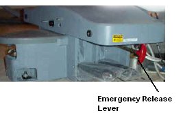
- Pull the Emergency Release lever at Dock and verify that the
Table is released. Push and restore the Emergency Release lever after
this test.
Figure 16. Emergency Release lever
- Perform Signal to Noise - Head Scan.