LCC Dock Replacement
Prerequisites
Procedure for replacement of the following dock components for 1.5T and 3.0T LCC Magnets.
-
The dock limit switch board.
-
The dock gear-motor and clutch assembly.
1 Removal of Dock
Procedure
 danger
- Perform ACGD Lock Out Tag Out.
- Undock the patient table and remove it from the scan room.
- Disconnect the two cables that are attached to the Dock. These should be the runs going to the Dock Assembly (MG2 A29) and the Dock Limit Switch (MG2 A31).
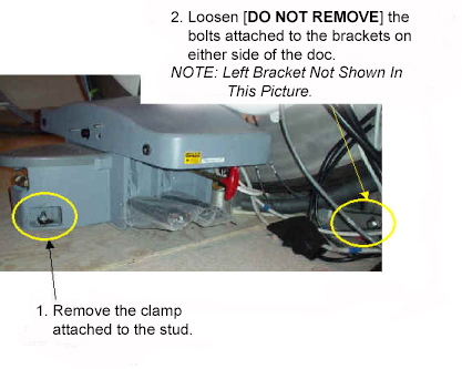
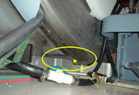
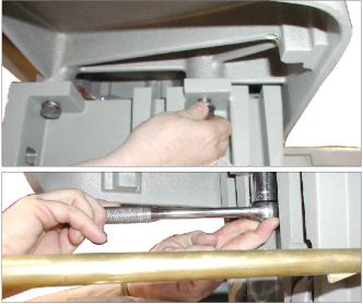
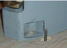
- Using a marker, mark the nut and clamp bracket before removal.
The marks will be realigned when the dock is installed later to ensure
proper tightening. See Figure 1.
Figure 1. Marking the Nut and Clamp Bracket
- Loosen the bolts attaching the dock assembly at the front and
at the right and left brackets. See Figure 2. (Figure 5 also shows
bolt locations).
Figure 2. LOOSEN DOCK ATTACHMENT BOLTS
- warning
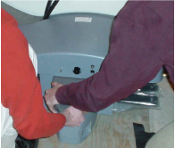
- Applying pressure to the top of the dock, completely remove
all dock attachment bolts. See Figure 3.
Figure 3. APPLY PRESSURE TO DOCK AND REMOVE ATTACHMENT BOLTS
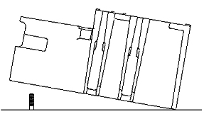
- Use two FEs to pull the dock away from the magnet until the
stud in the front is hitting the inner frame. See Figure 4.
Figure 4. PULL THE DOCK AWAY FROM THE MAGNET AS MUCH AS POSSIBLE
- warning
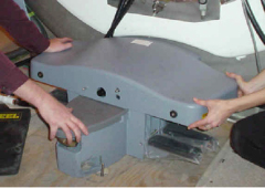
- Use two FEs to lift the dock up JUST ENOUGH to clear the top
of the stud in the floor. See Figure 5.
Figure 5. LIFT THE DOCK JUST ENOUGH TO CLEAR THE STUD IN THE FLOOR
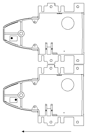
- The two FEs should gently place the dock to the left side of
the stud in the floor while still maintaining vertical downward pressure
to the dock. See Figure 6.
Figure 6. PLACE DOCK DOWN TO THE LEFT OF THE STUD IN THE FLOOR
 note:
note:It should not be extremely difficult for two FEs to pull the dock away from the magnet once all bolts are removed. If you do encounter difficulty, check that the brackets are not caught against the front of the magnet. See Figure 7.
Figure 7. WATCH FOR INTERFERENCE BETWEEN THE BRACKET AND THE MAGNET
- With two field engineers, one holding each side of the dock, slide the dock away from the magnet front to where the foot of the patient table would normally be located.
- When a safe distance away from the magnetic field (at least as far as the foot end of the patient table), two field engineers may slowly lift the dock from the floor and exit the room.
2 Replacement of Dock Limit Switch
Procedure
- The Dock Limit Switch should only be removed AFTER following the procedure above (Removal of Dock) for Removal of Dock.
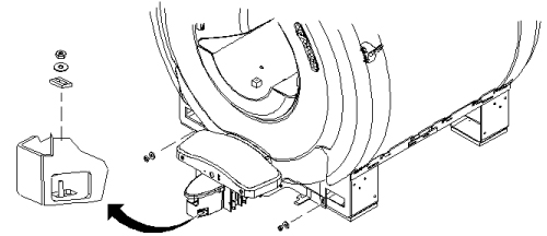
- To remove the Dock Control Assembly, see Figure 8.
Figure 8. REMOVAL OF THE DOCK CONTROL ASSEMBLY
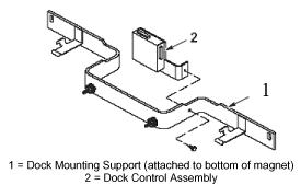
- Once the Dock Control Assembly has been detached from the dock mounting support, perform the remainder of this replacement procedure outside of the magnet room.
- To access the circuit board internal to the Dock Control Assembly,
see Figure 9.
Figure 9. REMOVAL AND REPLACEMENT OF DOCK LIMIT SWITCH BOARD
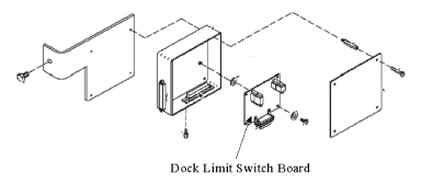
- Replace the Dock Limit Switch Board as shown in Figure 9.
- Re-assemble the Dock Control Assembly as shown in Figure 8.
- Re-attach the assembly to the Dock Mounting Support.
Realign the marks on the nut and clamp bracket when installing the dock. This is to ensure proper tightening.
Excessive tightening may result in the stud being pulled from the floor.
3 Replacement of Gear Motor and Clutch Assembly
Procedure
- warning
- The Motor and Clutch Assembly should only be removed AFTER completing the procedure for Removal of Dock, refer to Removal of Dock.
- Remove the upper cover of the dock by un-bolting the four hexbolts.
See Figure 10.
Figure 10. REMOVE FOUR HEXBOLTS FROM UNDER DOCK COVER
- Slightly lift the cover and disconnect all electrical connections between the cover and the base of the dock assembly. The connections will be the ground connection for the motor and the harness for the dock motor.
- Remove the dock cover from the base.
- Disconnect the motor's ground lug from the cover. See Figure 11.
Figure 11. MOTOR GROUND LUG REMOVAL

- Remove the four mounting screws for the motor. See Figure 12.
Figure 12. REMOVE MOTOR MOUNTING SCREWS
- Remove existing motor.
- Install replacement motor.
- Attach motor by replacing the four mounting screws for the motor. SeeFigure 12 for location of the screws.
- Attach the motor's ground lug to the cover. See Figure 11.
- Replace the dock cover on the base.
- Reconnect all electrical connections between the cover and the base of the dock assembly. The connections are the ground connection for the motor and the harness for the dock motor.
- Replace the upper cover of the dock and secure by replacing the four hexbolts. See Figure 10.
4 Installation of Dock
Procedure
- warning
- With two field engineers, one holding each side of the dock, enter the magnet room and place the dock on the floor where the foot of the patient table would normally be located.
- With two field engineers, one applying vertical downward pressure to each side of the dock, slide the dock toward the magnet front.
- While maintaining pressure to the top of the dock, position
the dock against the base of the magnet to the left of the floor stud
at the front of the dock. See Figure 13.
Figure 13. Placement of Dock
- Lift the dock just enough to clear the top of the stud in the
floor. See Figure 14.
Figure 14. Lifting Dock to Clear Floor Stud
- While rotating the dock to the right, align the hole at the base of the dock with the stud and place the dock down into position.
- Use the attachment bolts to secure the dock at the front stud
and side brackets. See Figure 15.
Figure 15. SECURE THE DOCK TO THE MAGNET
- Connect the cable to the Dock Assembly (MG2 A29) and to the Dock Limit Switch (MG2 A31).
- Remove the power lock- out tag-out from the ACGD cabinet and restore power.
- Align and dock the table.
Realign the marks on the nut and clamp bracket when installing the dock. This is to ensure proper tightening.
Excessive tightening may result in the stud being pulled from the floor.
5 What to do next
Finalization
No finalization steps.