HUB Replacement in System Cabinet
Prerequisites
Overview
Procedure
- Remove L Upper Front Cover and R Upper Front Cover and Rear Cover. SC Cover Removal.
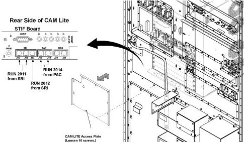
- To withdraw CAM Lite2 chassis, remove CAM Lite Access Plate
and check remove optical cables from STIF Board.
Figure 1. opt cable removal
- Disconnect the following connectors from front panel of CAM
Lite 2 and HUB.
-
Ethernet swith (HUB): port 6, port 7, port 8
-
UPM1, 2: J3
-
NB DET1, 2: J1, J4
-
NB AIF: J3, J5
-
IRF3: J8, J11, J13
-
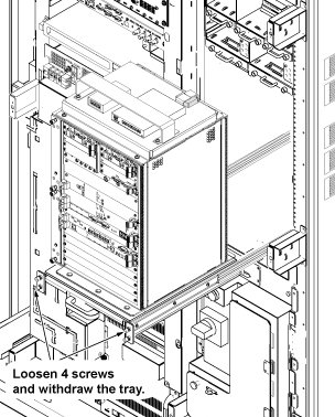
- Loosen 4 screws which are tightening CAM Lite 2 bracket and chassis.
- Withdraw CAM Lite Assy until it stops at stopper position.note:
When draw out the unit, be careful no to damage cables and unit.
Figure 2. Withdraw CAM Lite Assy
- Cut the tie-wraps fixing HUB power cable of CAM rear side.
- Disconnect all connectors and power cable from HUB.
- Disconnect the power cable or power adapter from SC inner panel.
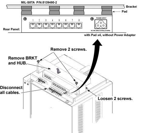
- Remove 2 screws from front side of support bracket, and loosen
2 screws fixing rear side of support bracket, and remove support bracket
and HUB.
Figure 3. HUB Removal
- Restore System Cabinet by reverse order of removal.
1 Finalization
Procedure
- Restore the Power. Refer to System Cabinet PDU Main Breaker LOTO Procedure.
- Open C Shell and type as follows. Check that result of each ping test is ok.
- ping agp [Enter]
- ping scp [Enter]
- ping vre [Enter]
- Perform Signal to Noise - Head Scan.