Ground Leakage Current Test
Prerequisites
Before performing this procedure, you must have completed proper electrical hazard training courses, including
-
Power and Grounding Audit (GEHC-TECH-AMOL-CM9010) or equivalent
-
Electrical Safety Authorized Course (GE-EHS-280) or equivalent
Be sure to understand Preliminary Requirements Before Beginning this Procedure.
1 Ground Leakage Current Test Using DVM and 1kOhm Resistor Procedure
Procedure
- Perform PDU LOTO procedure, refer to Lockout / Tagout for MDP(Main Disconnect Panel) or Facility PDU.
- Verify that Main Disconnect and PDU indicators lights are off, and that power switches are inactive.
- Connect 1k Ohm resistor to PDU ground bus bar. See Figure 1
Figure 1. Leakage Current Resistor Hookup
 note:
note:Some subsystem cabinets have one ground connection at the PDU bus bar, while other subsystem cabinets have two. If two ground connections exist, be sure that both are disconnected in the following step.
note:Most subsystem cabinet grounds are incorporated within power cables. Refer to the "System Interconnects" illustration provided in the installation manual for locating subsystem cabinet grounds.
- At PDU bus bar, disconnect ground connection(s) of subsystem
cabinet under test.note:
In the following step, only one ground cable should be connected to the 1K ohm resistor. If a second ground cable exists, leave it disconnected during test.
- Using jumper, connect one of the ground cable disconnected in Step 4 to unconnected end of 1K Ohm resistor. See Figure 1.
- Connect DVM across 1K Ohm resistor (to measure AC volts).
- Turn on facility disconnect or MDP
- Turn on Main Circuit Breaker on PDU.
- Measure voltage across 1K Ohm resistor.
- If subsystem cabinet under test only had one ground connection at PDU ground bus bar, verify that less than 500 mV (500 µA (0.5mA)) is measured. If more than 500 mV (500 µA (0.5mA)) is measured, a second ground cable must be added between subsystem cabinet under test and PDU ground bus bar. Furthermore, if more than 5000 mV (5000 µA (5mA)) is measured, a serious leakage current problem exists which must be corrected. Use appropriate procedures to troubleshoot system.
- If subsystem cabinet under test had two ground connections at PDU ground bus bar, verify that less than 5000 mV (5000 µA (5mA)) is measured. If more than 5000 mV (5000 µA (5mA)) is measured, a serious leakage current problem exists which must be corrected. Use appropriate procedures to troubleshoot system.
note:500mV corresponds to 500 µA (0.5mA) of leakage current.
- Turn off PDU power (Main Circuit Breaker).
- Turn off MDP or facility disconnect.note:
Some subsystem cabinets have one ground connection at the PDU bus bar, while other subsystem cabinets have two. If two ground connections exist, be sure that both are reconnected in the following step.
- At PDU ground bus bar, reconnect ground connection(s) of subsystem cabinet under test.
- Perform Step 1 through Step 12 for each subsystem cabinet.
- System Restoration
- Remove DVM leads.
- Remove 1K Ohm resistor and jumper.
- Close System cabinet.
- Remove LOTO.
2 Ground Leakage Current Test Using Safety Analyzer
2.1 Performing LOTO
Procedure
- Properly shut down the system (if the host computer is up).
- Perform LOTO procedure. Lockout / Tagout for MDP(Main Disconnect Panel) or Facility PDU.
- With a digital voltmeter (DVM), check that all energy has dissipated. Confirm that the PDU indicators lights are OFF.
2.2 Setting Up Safety Analyzer
Procedure
- Set up the safety analyzer near the front of the PDU.
-
Using the Dale Safety Analyzer:
- Connect one clamp-type lead to the EXTERNAL jack on the top of the Dale safety analyzer. Connect the other clamp-type lead to the CHASSIS jack on the top of the Dale safety analyzer.
- On the Dale safety analyzer, set the main selector switch to EXTERNAL.
Figure 2. Connections on Dale Safety Analyzer
-
Using the Fluke ESA612 Safety Analyzer:
- note:Turn on the Fluke safety analyzer.
At facilities with 110-120 VAC, a fault error may appear when you power the meter on. Press F4 OK to clear the error, and continue.
Figure 3. Fluke ESA612 Electrical Safety Analyzer
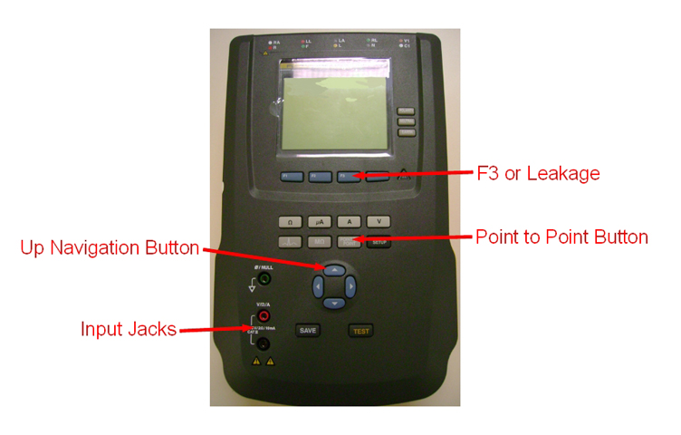
- Select the [point to point] button.
- Select the [F3 or Leakage] button.
- Select the [Up Arrow] once so that AC Only displays.
- Insert the leads into the input jacks.
- The safety analyzer is now set up with the two leads attached and ready to be connected to the PDU.
Two types of safety analyzers are available. Use the instructions for the safety analyzer that is available.
2.3 Measurement
Procedure
- Connect the Chassis clamp-type lead to PDU ground bus bar.note:
Some subsystem cabinets have one ground connection at the PDU bus bar, while other subsystem cabinets have two. If two ground connections exist, be sure that both are disconnected in the following step.
note:Most subsystem cabinet grounds are incorporated within power cables. Refer to the "System Interconnects" illustration provided in the installation manual for locating subsystem cabinet grounds.
note:In the following step, only one ground cable should be connected to the External clamp-type lead. If a second ground cable exists, leave it disconnected during test.
- At PDU bus bar, disconnect ground connection(s) of subsystem cabinet under test. (Ground leads on the PDU bus can best be reached by opening the front cover of the PDU. The ground leads can be removed using appropriate deep sockets.)
- Connect one of the ground cable disconnected in the previous step to External clamp-type lead.
- Turn on MDP or facility disconnect.
- Turn on PDU power (Main circuit breaker).
- Measure leakage current.
- If subsystem cabinet under test had only one ground connection at PDU ground bus bar, verify that less than 500 µA (0.5mA) is observed. If more than 500 µA (0.5mA) is measured, a second ground cable must be added between subsystem cabinet under test and PDU ground bus bar. Furthermore, if more than 5000 µA (5mA) is measured, a serious leakage current problem exists which must be corrected. Use appropriate procedures to troubleshoot system.
- If subsystem cabinet under test had two ground connections at PDU ground bus bar, verify that less than 5000 µA (5mA) is measured. If more than 5000 µA (5mA) is measured, a serious leakage current problem exists which must be corrected. Use appropriate procedures to troubleshoot system.
- Turn off PDU power (Main Circuit Breaker).
- Turn off MDP or facility disconnect.note:
Some subsystem cabinets have one ground connection at the PDU bus bar, while other subsystem cabinets have two. If two ground connections exist, be sure that both are reconnected in the following step.
- At PDU ground bus bar, reconnect ground connection(s) of subsystem cabinet under test.
- Perform Step 1 to Step 9 turning on appropriate circuit breakers for each subsystem cabinet under test.
- System Restoration
- Remove the leads from the safety analyzer.
- Close System cabinet.
- Remove LOTO.
3 Finalization
Procedure
- Ensure the system is ready for patient scanning.