Ground Resistance Checks
Prerequisites
This document contains a method for measuring ground resistance using different brands of safety analyzers. Only one of the safety analyzers listed in Tools and Test Equipment is required for this procedure.
Review and understand the required conditions before beginning this procedure.
1 Ground Resistance Checks Using Microguard
Procedure
 danger
- Ensure that no power is applied to PDU, see Lockout / Tagout for MDP(Main Disconnect Panel) or Facility PDU.
- Notify all Field Service Engineers working at the site that PDU Main Disconnect will be shut off and locked out.
- Locate and shut off the Main Disconnect supplying power to the PDU.
- Verify that the Main Disconnect and PDU indicator lights are off, and that power switches are inactive.
- With a digital voltmeter (DVM), check that all energy has dissipated.
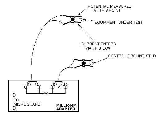
- Plug milliohm adapter module into power outlet of the Microguard.
Figure 1. MICROGUARD CONNECTIONS
 note:
note:Since the Microguard is being used solely as a voltmeter in this application, any other meter capable of resolving 0.1 millivolts can be substituted in the next step. Meters other than the Microguard are currently in use. Refer to the appropriate tool catalog for further information.
- Attach Microguard red and black leads to meter posts of milliohm module.
- Set Microguard Patient Lead Tester switch to All Other Tests.
- Set Microguard Selector switch to 20 Microamps/Millivolts.
- Set Microguard Input switch to Red and Black Probes.
- Attach the Kelvin leads as shown in Figure 1. (Connect one lead to PDU ground bus bar, and the other lead to frame of subsystem cabinet under test.)
- The meter reads voltage across ground resistance in millivolts. To obtain resistance in milliohms, multiply meter reading by 2.
- Verify that measured resistance is less than 100 milliohms (corresponding to a meter reading of 50 millivolts). If this fails, recheck and reposition the lead connections and inspect the power cable connection. If the reading fails, add an additional ground cable to the cabinet that is failing.
- Perform Step 11 through Step 13 for each subsystem cabinet.
- System Restoration
-
Turn Microguard power off.
-
Remove leads and milliohm adapter from Microguard.
-
Close all subsystem cabinets and System cabinet.
-
2 Ground Resistance Checks Using Dale (Sites Equipped with Dale 600, 600E, 601, or 601E Safety Analyzer)
Procedure
- danger
- Perform PDU LOCKOUT TAGOUT. See Lockout / Tagout for MDP(Main Disconnect Panel) or Facility PDU.
- Notify all Field Service Engineers working at the site that PDU Main Disconnect will be shut off and locked out.
- Locate and shut off the Main Disconnect supplying power to the PDU.
- Verify that Main Disconnect and PDU indicators lights are off and power switches are inactive.
- With a digital voltmeter (DVM), check that all energy has dissipated.
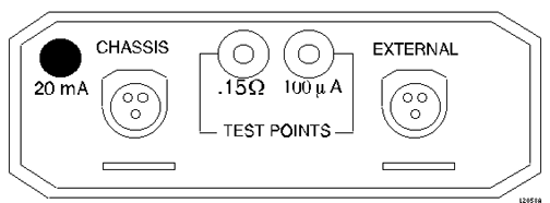
- Connect one clamp-type lead to the EXTERNAL jack on the top of the Dale safety analyzer. Connect the other clamp-type
lead to the CHASSIS jack on the top of the
Dale safety analyzer. See Figure 2.
Figure 2. TOP OF DALE SAFETY ANALYZER
- On the Dale safety analyzer, set the main selector switch to W - RESISTANCE. See Figure 3.
Figure 3. DALE SAFETY ANALYZER
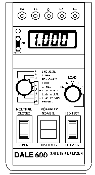
- Plug the Dale into an AC outlet.
- On the Dale safety analyzer, verify that the two OK LEDs light up to indicate that the AC outlet is properly wired. See Figure 3.
- With leads not touching each other, the display should read 1.00. With the leads touching (copper to copper) the display should read 0.00 to 0.02.
- Attach the leads as shown in Figure 4.
(Connect one lead to PDU ground bus bar and the other lead to bare
frame of subsystem cabinet under test.)
Figure 4. DALE 600/600E ANALYZER
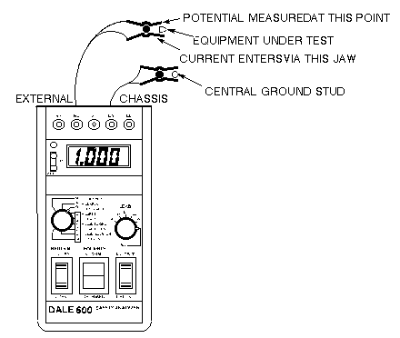 note:
note:The Dale safety analyzer reads resistance in ohms. For example, a reading of 0.50 equals 500 milliohms.
- Verify that measured resistance is less than 100 milliohms (corresponding to a meter reading of 50 millivolts). If this fails, recheck and reposition the lead connections and inspect the power cable connection. If the reading fails, add an additional ground cable to the cabinet that is failing.
- Perform Step 11 through Step 12 for each subsystem cabinet.
- System Restoration
- Unplug Dale from the AC outlet.
- Remove leads from the Dale.
- Close all subsystem cabinets and PDU cabinet.
3 Ground Resistance Checks Using Fluke ESA612
Procedure
- danger
- Ensure that no power is applied to the MDP. See the MR Service Safety Manual, PN 5452735.
- Notify all Field Service Engineers working at the site that the MDP is being shut off, locked out, and tagged out.
- Locate and shut off the MDP which supplies power to the PDU.
- Check that the MDP and PDU indicator lights are off, and the power switches are inactive.
- With a digital voltmeter (DVM), check that all energy has dissipated.
- Turn on the Fluke meter and select the point to point option on the meter.
Figure 5. Fluke ESA612 Safety Analyzer
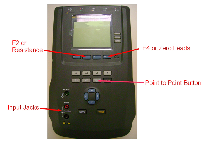
- Select resistance or F2.
- Attach the leads into the red and black input jackets and short the leads together.
- Select zero leads or F4.
- Connect one lead to the PDU ground bus bar and the other lead to the bare frame of the subsystem cabinet under test.
- Verify that measured resistance is less than 100 milliohms (corresponding to a meter reading of 50 millivolts). If this fails, recheck and reposition the lead connections and inspect the power cable connection. If the reading fails, add an additional ground cable to the cabinet that is failing.
- Repeat Step 10 through Step 11 for the remaining cabinets:
- Restore the system.
- Turn off the Fluke safety analyzer.
- Remove the leads from the analyzer.
- Close all subsystem cabinets and the System cabinet.
At facilities with 110-120 VAC, a fault error may appear when you power the meter on. Press F4 OK to clear the error, and continue.
4 Finalization
Procedure
- Remove LOTO from the MDP and restore power.
- Perform a goodbye scan.