Grafidy3 Procedure
Prerequisites
1 Hardware Set-Up
Procedure
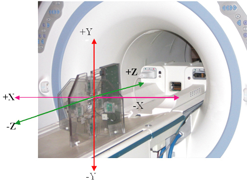
- Unfold the 6-channel grafidy fixture and lock the arms into place (90o from center plate).
- Connect Hypertronics cable to T/R board and use screws to secure. Place the fixture at the front (Head coil end) of the MR table with the connection box toward the bore.
- Plug the Hypertronics connector into the Port A. (The Green
Coil ID light will come on.)
Figure 1. Grafidy Hardware Setup
 note:
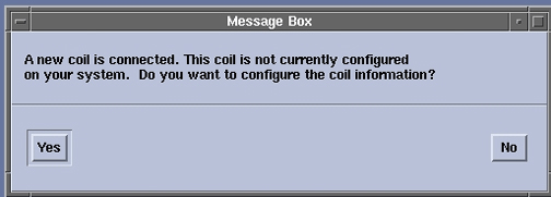
note:The very first time a Grafidy Coil is connected to the system, a popup may announce that “A New Coil Is Connected”. Click the Yes button to add the coil configuration to the system. You shouldn't see this message again unless software is reloaded.
Figure 2. A New Coil Is Connected Popup
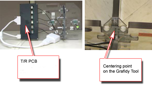
- Center the laser cross hairs on top of the fixture. Landmark
the system and press Advance to Scan.
Figure 3. Grafidy Tool And The Centering Point
2 Running Grafidy 3
Procedure
- Start the Grafidy 3 tool.
-
Starting non-proprietary service tools: From the Common Service Desktop, select Calibration, Grafidy3 from the calibration menu, and select Click here to start this tool to start the procedure.
-
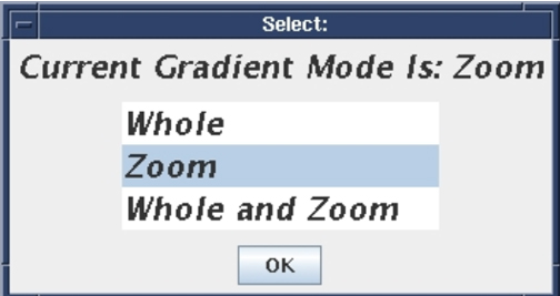
- For Twin Systems, the tool will ask you to select a gradient
mode (see Figure 4) . Both modes need to be calibrated, and you
may start with either one. note:
For the WHOLE (i.e the first mode) , ZOOM (i.e. the second mode), continue with the next step. For the WHOLE and ZOOM (i.e. the third mode), go to Step 6.
(To switch modes, you will need to exit, and restart Grafidy 3 in the other mode.)
Figure 4. Selecting Gradient Mode
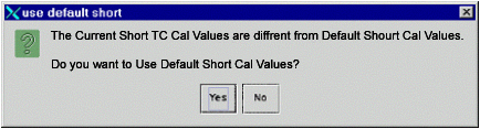
- If you receive the message shown below about “Short TC Cal Values”, click Yes.
Figure 5. Default Short Cal Values Popup
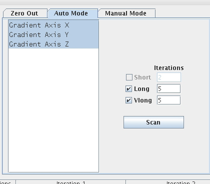
- Click on the Auto Mode tab. All three-coil
axes will be selected. Click the Scan button
to start the calibration. (When the scan is active, you can stop it
by pressing the Abort button and the “STOP” button on keyboard.)
Figure 6. Auto Mode Setup
 note:
note:When in Auto/Manual Mode, a number of signal checks are performed to ensure the proper state of the grafidy fixture. The following signals are examined from every channel and an error is reported if a problem is found. The signals are as follows:
-
Position.
-
SNR.
-
Signal Saturation.
-
- If you did the tests for WHOLE / ZOOM already, proceed to Step 9. Else continue to Step 6.
- For the Whole and Zoom Procedure, select the “Whole and Zoom” option and press the “OK” button (as shown in Figure 4) and the scan takes place automatically. It will scan first in the WHOLE mode and then the ZOOM mode .It will then give a pop-up as shown in the Step 9.
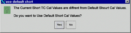
- If you receive the message shown below about “Short TC Cal Values”, click Yes.
Figure 7. Default Short Cal Values Popup
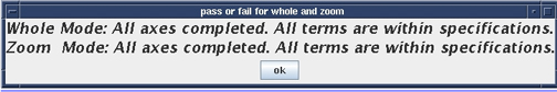
- The Tool will perform the tests in both the WHOLE and ZOOM mode
and give pop-up as shown below.
Figure 8. Pop-up After The Scan Concludes Successfully In The WHOLE And ZOOM Mode
- The Grafidy 3 software runs multiple scans to bring each term
into specification. It iterates up to the maximum specified (default
is 5 iterations). The WHOLE or ZOOM mode usually takes about 2 hours.
As each component finishes a scan/analysis iteration, the residual of the eddy current of the measurement displays in the results table. The results are color-coded, see Table 6.
- Review the numeric output values from the auto mode scan. Verify
that the results of final iteration for each component are below specs
(green). See below for help in reading output values.
Figure 9. Reading The Output : The specs and the Actual values (Smoothed) are shown circled.
- If a component is not in spec after the maximum number of iterations you may need to use manual mode to calibrate that component. See Manual Mode.
- If system type is TRM, and if you have already done Whole or Zoom mode, repeat the calibration procedure for the other gradient mode. When you are finished, quit the tool by pressing the EXIT button. Note that this step is not required for the “WHOLE and ZOOM” mode
Systems with S5 magnets should have Very Long Eddy Currents rechecked in manual mode after 10 minutes, as it is possible for calibration to drift and require additional adjustment.
3 Manual Mode
Use Manual Mode when Auto Mode fails to bring one or more of the terms into specification. Manual Mode lets you iterate through the process yourself, and decide when to stop.
Procedure
- Select the [Manual Mode] tab.
Figure 10. Manual Mode Tab
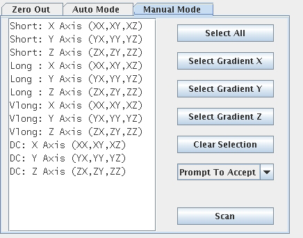
- Select the desired terms, and then press Scan.
- If the “Prompt To Accept” mode is active, after
the scan is complete, a graph of the results will pop up. In order
to learn about “Prompt To Accept” refer to Grafidy 3 Tools, section
7, manual mode.
Figure 11. Results Window With Accept/Cancel Buttons
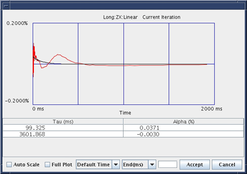
- If a “good fit” is shown, click the Accept button. The calibration values will be saved to disk, and these values will be used in the next scan. Repeat this process by going back to Step 2.
- If a “bad fit” is shown, click Cancel. This will leave the last accepted values in the calibration files. Do not expect any improvement on future scans when the fit doesn’t match the data even if you accept the cal parameters.
- The last iteration for any component must be a check only, and you should not accept the fit parameters. You will not be allowed to exit immediately after updating the cal parameters.
- In order to know more about Grafidy, refer to Grafidy 3 Tools.
4 Finalization
Procedure
- Remove Fixture from the system.
- Exit the Software Tool.