Cable and Track Assy Replacement
Prerequisites
Procedure
- Remove LPCA Cover. Refer to LPCA Cover Removal.
- Remove all covers from Rear Pedestal.
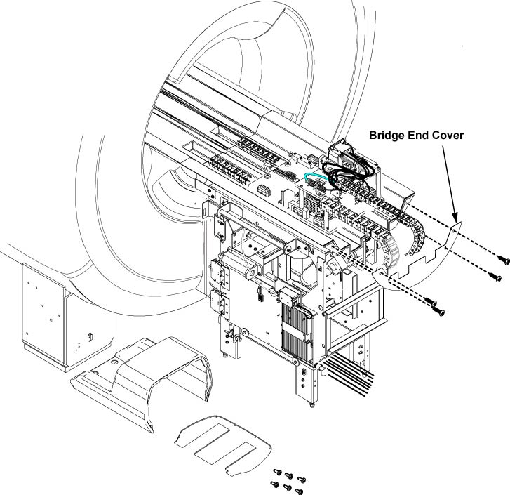
- Remove Bridge end cover.
Figure 1. Bridge end cover
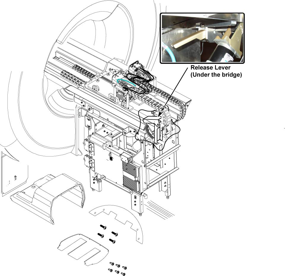
- Release the lever for the belt tension.
Figure 2. Release the lever
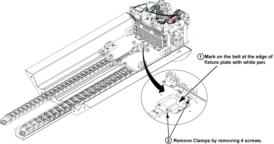
- Mark on the belt at the edge of fixture plate with white pen so that the belt tension can be restored it is after the replacement.
- Remove belt fixture plates.
Figure 3. Belt fixture plates
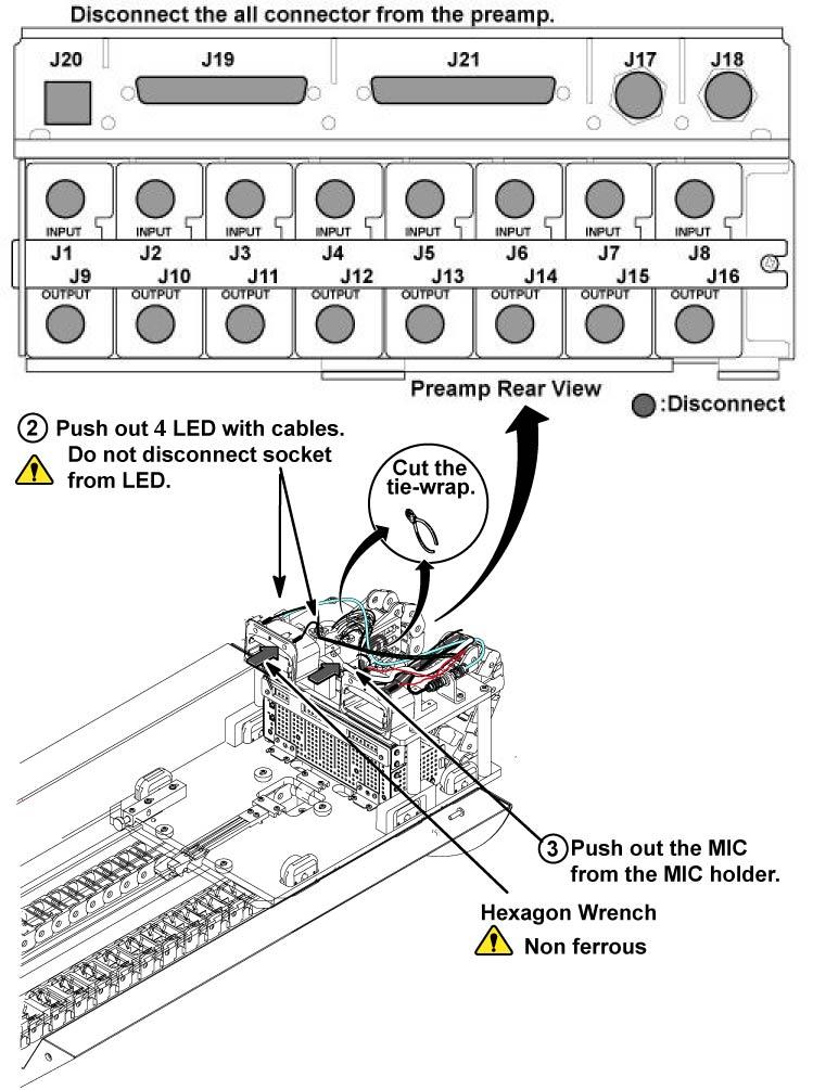
- Cut 2 tie wraps from LPCA.
- Remove the following connectors. (J18 BNC, Sub-D Connector J21,
J9 – J16 BNC connectors from MC pre-amp (Input Side), 2 LED cable-With
LED, MIC)
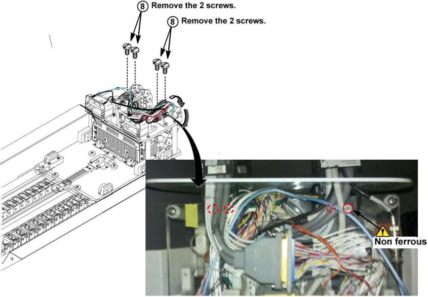
Figure 4. Remove connectors
- Remove 2 screws from cable and track assy.
Figure 5. 2 screws
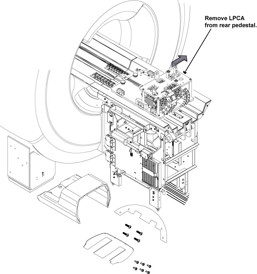
- Remove the LPCA from the Rear pedestal.
Figure 6. Remove the LPCA
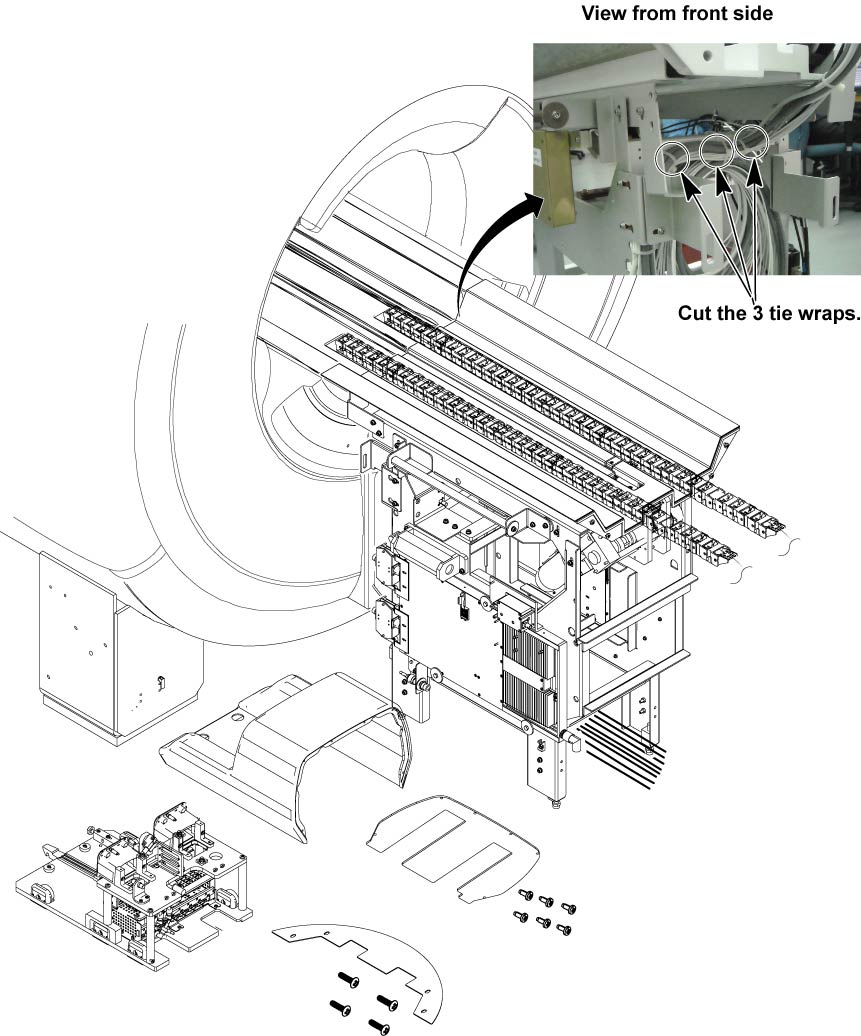
- Cut 3 tie wraps at the rear pedestal top front chassis.
Figure 7. Cut tie wraps
- Remove 3 cables from Maga switch (J15, J18 and J21 connectors),
Remove 3 cables from Rear Pedestal. (Left side: J7 connector. Right
side: BNC of Dummy Load and J1 connectors.)
Figure 8. Remove cables
- Remove 4 screws from bracket.
Figure 9. screws at bracket
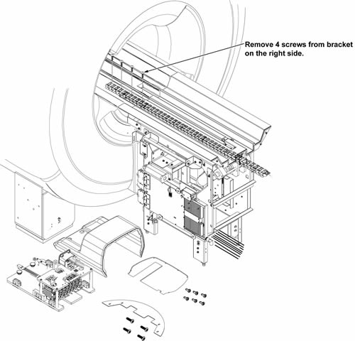
- Remove Cable and track assy with bracket.
- Move the Cable and track assy with bracket to the open space. (Outside of Magnet Room)
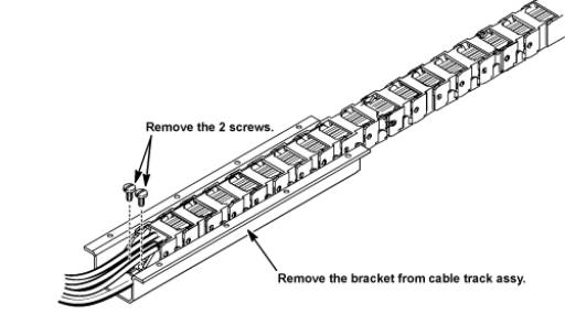
- Remove 2 screws and remove bracket from track assy.
Figure 10. track assy
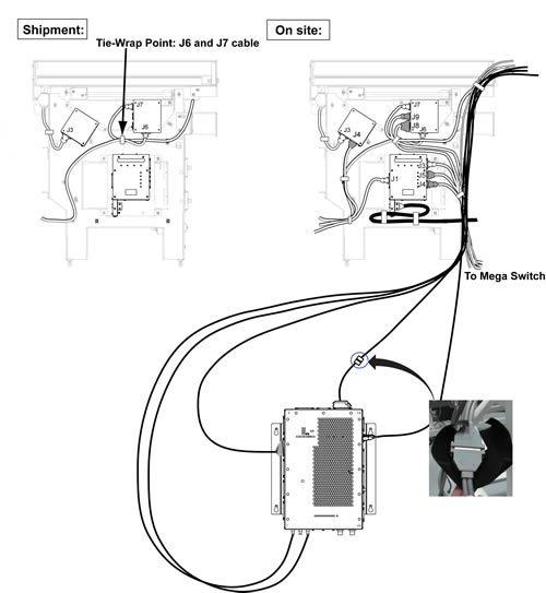
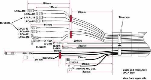
- Restore Cable and Track Assy by the reverse order of the removal.note:
The all tie wraps and cables length must be fixed at the same as illustration 11.
Figure 11. Tie-wrap Points
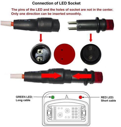
 note:
note:Connect the LED cable so that the cable is centered to the LED itself.
Figure 12.
Finalization
- Restore the Power. Refer to Lockout / Tagout for System Cabinet PDU Main Breaker.
- Run MCR tool.
- Run one head or body scan.