CSA
Prerequisites
Procedure
- Remove L Upper Front Cover. Refer to SC Cover Removal.
- Drain the coolant. Refer to Draining Operation before replacing CSA, XFA, or XFD-PS..
 warning
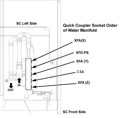
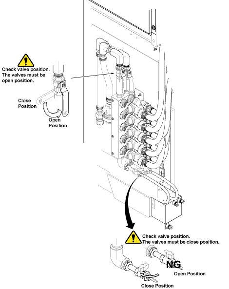
- Disconnect the IN and OUT quick couplers of CSA from the water
manifold.
Figure 1. Water Manifold Socket Order
- caution
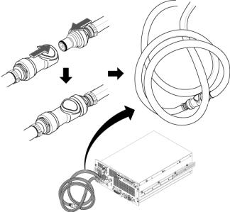
- Connect the IN and OUT quick couplers of CSA, and tie the hose
as illustration.
Figure 2. Water Manifold
- Disconnect the all connectors from front panel of CSA.
- Set the Universal Lift Hoist onto SC top. Refer to Hoist Setup.
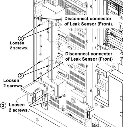
- Disconnect the two connectors of leak sensor assy.
- Remove the cabinet leak sensor assy by loosening 6 screws.
Figure 3. Remove Leak Sensor Assy
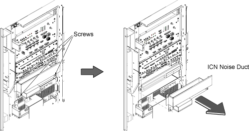
- On the front of the ICN, remove the three screws and remove
ICN Noise Duct.
Figure 4. Remove ICN Noise Duct
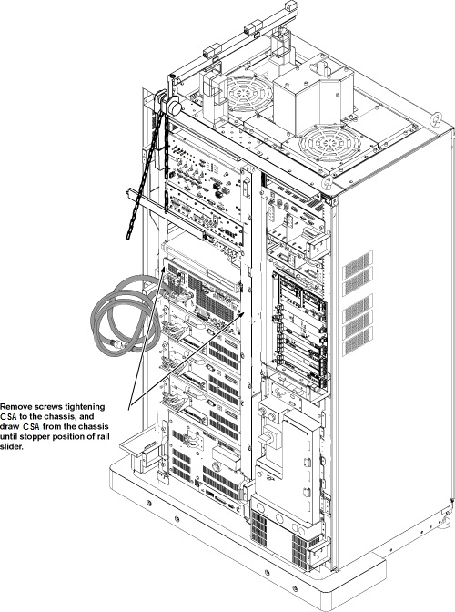
- Remove 4 screws which are tightening CSA front panel to the chassis.
- Withdraw CSA from the chassis until it stops at stopper position
of slider rail.
Figure 5. Withdraw CSA
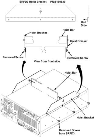
- Install the two hoist brackets to the chassis of CSA with 6 removed screws. Do not tighten 6 screws of hoist brackets.
- Install the hoist assembly to the hoist brackets of CSA, and
tighten 6 screws of hoist brackets. Check that hoist bracket and hoist
assembly are installed surely.
Figure 6. Attach Hoist Bracket
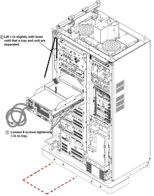
- Loosen 8 screws which are tightening CSA chassis to tray.
- LIFT CSA slightly with hoist. Check that tray and CSA separated completely.
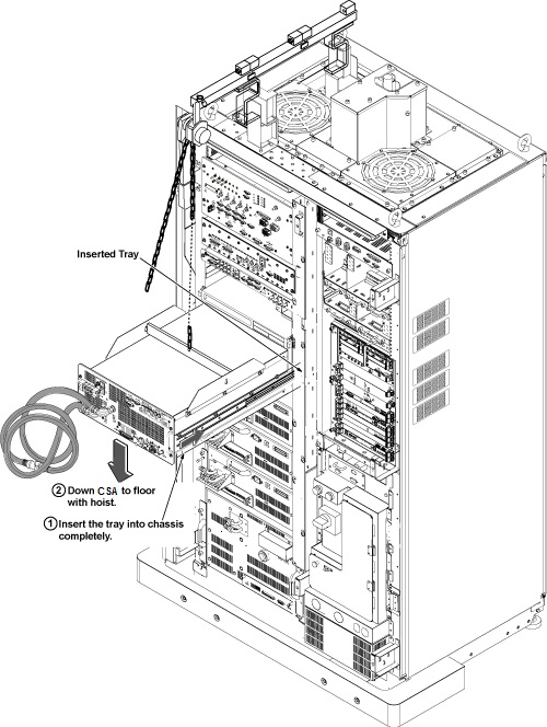
- Insert the tray into the chassis completely.
Figure 7. Hoist Operation
- notice
- Use the hoist and slowly lower the CSA Chassis to the floor.
Remove the two hoist brackets from CSA chassis.
Figure 8. Hoist Operation
- Install CSA by the reverse order of the removal.note:
Make sure to connect all cables and hoses.
note:Make sure to close draining valves and open Supply and Return valves.
- Restore System Cabinet.
 |
|
 |
Finalization
- Restore the Power. Refer to System Cabinet PDU Main Breaker LOTO Procedure.
- Refill Coolant. Refer to Refill Coolant after replacement of CSA, XFA, or XFD-PS.
- Perform RF Output Power Check. Refer to Body and Head Maximum Power Setup and Calibration.
- Perform UPM Functional Check. Refer to UPM- Body and Head Functional Check .
- Perform Signal to Noise - Head Scan.