Draining Operation before replacing CSA, XFA, or XFD-PS
Prerequisites
Procedure
- Remove L Front Cover and Water Manifold Access Cover. Refer to SC Cover Removal.
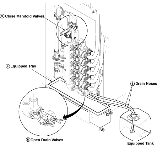
- Close the Manifold Valves. See Figure 3.
- Take out the two draining hoses from drip pan.
- To set the equipped water tray on drip in Step 5, sensor cables
will interfere. Disconnect the connectors of sensor cable to set water
tray. Be sure not to forget to re-connect after draining procedure.
- Set equipped water tray on drip for false operation prevention of a sensor. See Figure 3.
- Set the drain hoses to the equipped coolant tank. See Figure 3. (The opening
of equipped coolant tank is a little bit small for two drain hoses.
But, it is possible to insert two hoses.)note:
The Equipped Coolant Tank is found in the drip pan of SC left side.
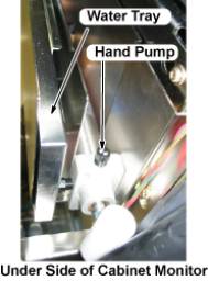
note:The water tray and hand pump are found in the under side of cabinet monitor.
Figure 1. Location of Coolant Tank
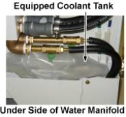
Figure 2. Location of Water tray, and Hand Pump
- notice
- Open the drain valves. See Figure 3.
Figure 3. Open Drain Valve
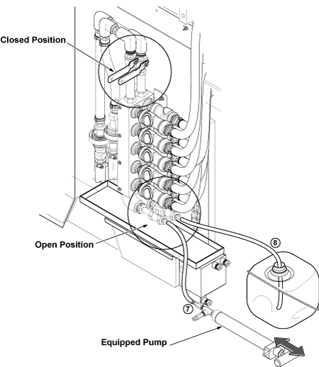
- Connect equipped hand pump to hose of one side, and push out remaining coolant.
- Connect pump to hose of opposite side and insert the other hose to the tank. Then, push out remaining coolant.
-
Figure 4. Setup and push out coolant
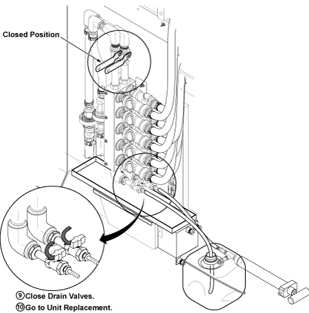
- Close drain valves surely.
Figure 5. Close Drain Valve
- Return the drained coolant to tank of LCS or MCS.
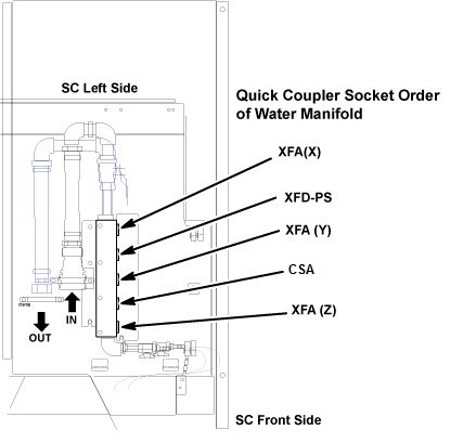
- Go to CSA, XFA, or XFD-PS unit replacement.
Figure 6. Water Manifold Socket Order
 |
Finalization
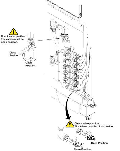
- After Replacement is done, make sure to close draining valves
and open Supply and Return valves.
Figure 7. Restoration
- Restore Water Tray and Coolant Tank.
- Restore draining hoses as it was.
- Connect sensor cables which are disconnected in Step 4.
- Restore Covers.