CRADLE EMERGENCY RELEASE CHECK AND ADJUSTMENT
Prerequisites
1 Cradle Emergency Release Adjustment Check
Procedure
- Twist handle fully to extend release bar.
Figure 1. Twist handle fully
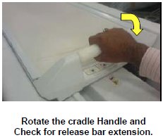
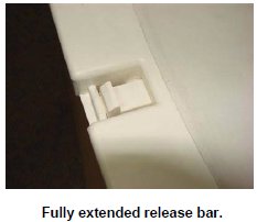
- Check for release bar extension when handle twisted fully.
Figure 2. Check for release bar extension
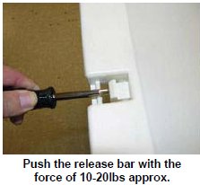
- Twist Handle fully to extend release ramp as shown in Figure 1 and Hold it at the extended position.
- Push the “Release Ramp” using a socket extension,
nut driver, or similar tool with approx. 10-20 lbs force as shown
in Figure 3. Observe the movement of the release ramp.
A properly adjusted release ramp will exhibit some spring and when
release will return to its original position. If the “Release
Ramp” fails to return to its original position and moves more
than Approx. 1.5mm (.06 in.) then adjust the release mechanism tension
per instructions in Cradle Emergency Release Adjustment.
Figure 3. Push the “Release Ramp”
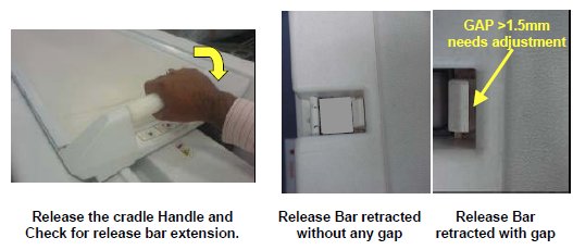
- Check for release bar retraction when handle released to its
original position and Release bar should be flushed against the cradle
front section as shown in Figure 4. If gap is observed
between the cradle and release bar adjust the release mechanism tension
as per instructions in Cradle Emergency Release Adjustment.
Figure 4. Check for release bar retraction
2 Cradle Emergency Release Adjustment
Procedure
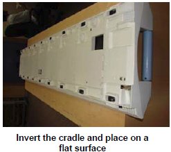
- Remove the Cradle from the table and take it out of the magnet room. Refer to Posterior Array Coil Replacement without removing Fixed Table or Posterior Array Coil Replacement with removing Fixed Table
- Invert the cradle and place on a flat surface.
Figure 5. Place the cradle
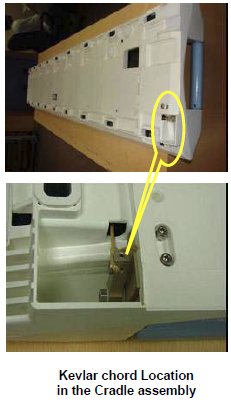
- Cradle Emergency release is actuated by a release bar, which
is connected by a Kevlar chord to the Lever. Refer Figure 6 for the Kevlar chord Lock in the Cradle.
Figure 6. Kevlar chord to the Lever
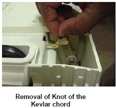
- Remove the Kevlar cord knot in the Cradle Rear section.
Figure 7. Kevlar cord knot
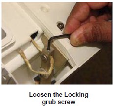
- Loosen the Kevlar chord locking by loosening the grub screw
by three rotations.
Figure 8. Loosen the Kevlar chord locking
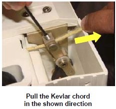
- Pull the Kevlar cord in the direction, and ensure proper tension
induced into Kevlar cord.
Figure 9. Pull the Kevlar cord
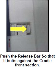
- Push the Release Bar to butt against the Front section.
Figure 10. Push the Release Bar
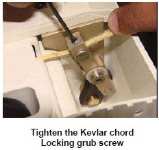
- Tighten the Kevlar chord locking grub screw.
Figure 11. Tighten the Kevlar chord locking grub screw.
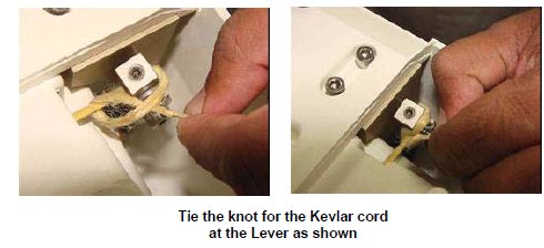
- Tie a knot for the Kevlar cord.
Figure 12. Tie a knot for the Kevlar cord
Finalization
No finalization steps.