Blower Box Motor Replacement
Prerequisites
The BRM Blower Box contains two blowers; one provides cooling air to the gradient body coil, the other provides cooling air to the patient comfort module. The blowers are AC induction motors. Since they do not have brushes, the entire motor is replaced.
1 Power Down and LOTO
2 Blower Location and GAP Check of between Rear pedestal and Wall
Procedure
- Check the Blower Box location and the gap between Rear pedestal
and Wall.
Figure 1. Blower Box location and gap check
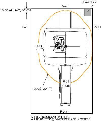
- If Blower Box is located at left side, go to next Section Remove Blower Box Motor Panel Assembly.
- Even though Blower Box is located at right side, if the gap between Rear pedestal and Wall is more than 15.7inch (400mm), go to next section Remove Blower Box Motor Panel Assembly.
- If the Blower Box is located at right side of magnet room and
the gap between Rear pedestal and Wall is 15.7inch (400mm) or less
as Figure 1, it is necessary to keep the service path first. Please proceed
following two steps.
 caution
- In this case, remove the Motor Assy first by referring to Interim Drive Assy Replacement.
- Then, turn the Rear Pedestal by 90 degree as Figure 2 by referring
to Rear pedestal Removal.
Figure 2. Turn Rear Pedestal by 90 degree

3 Remove Blower Box Motor Panel Assembly
Procedure
- Remove the power cables, air hoses and ground cable from the
blower box. (See Figure 3.)
Figure 3. Blower Box
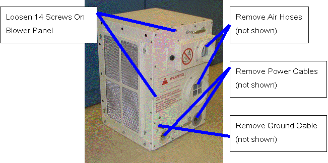
- Loosen, but do not fully remove the 14 screws securing the blower box motor panel assembly to the blower box. (See Figure 3.)
- danger
- warning
- caution
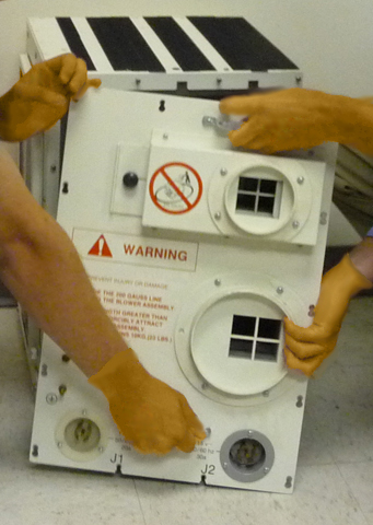
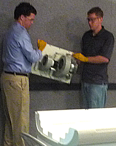
- With two people holding the handles, slide the blower box motor
panel assembly up and pull it slightly away from the blower box. See Figure 4.
Figure 4. Blower Box Motor Panel Assembly – Handle with Two People
- With two people holding the motor panel assembly, exit the magnet
room by walking as close to the wall on the coldhead side of the magnet
as possible. See Figure 5.
Figure 5. Blower Box Motor Panel Assembly – Handle with two people
|
To ensure a safe distance, make sure that the clear path through which you will be moving the blower box is completely outside the 200G line. The distance to the 200G line can be found in the Pre Installation Manual (PIM). (To open the PIM, from the Service Methods media navigate to the “Pre Installation” section and select the PIM corresponding to the system on which you are working. Gauss plots can be found in the section titled “MR Suite Minimum Room Size Requirements”).
THE 200G LINE MAY NOT BE WITHIN THE MINIMUM SERVICE AREA. IF THERE IS NOT ENOUGH ROOM TO MOVE THE BLOWER BOX OUTSIDE OF THE 200 GAUSS LINE, THE MAGNET MUST BE RAMPED DOWN PRIOR TO CONTINUING.
4 Replace Blower Motor
Procedure
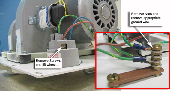
- Disconnect the wiring (shown in Figure 6) from the failed motor.
Figure 6. Blower Wire Removal
- Remove the failed motor from the panel. (See Figure 7.)
Figure 7. Blower Removal
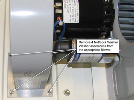
- Install the replacement motor on the panel, and secure it with 4 nut/lock washer/washer assemblies.
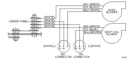
- Reconnect the motor wiring. (See Figure 8.) Strip 10 to 13 mm (3/8 – 1/2 in.) of insulation from each wire.
-
For HOT and NEU wires, insert the wire into the connector and tighten the set screw.
-
For GN1 or GN2 wires, terminate the wire with a 6 mm (1/2 in.) ring terminal and connect it to the ground stud.
Figure 8. Motor Panel Wiring Diagram
-
5 Install Blower Box Motor Panel Assembly
|
|
|
To ensure a safe distance, make sure that the clear path through which you will be moving the blower box is completely outside the 200G line. The distance to the 200G line can be found in the Pre Installation Manual (PIM). (To open the PIM, from the Service Methods media navigate to the “Pre Installation” section and select the PIM corresponding to the system on which you are working. Gauss plots can be found in the section titled “MR Suite Minimum Room Size Requirements”).
THE 200G LINE MAY NOT BE WITHIN THE MINIMUM SERVICE AREA. IF THERE IS NOT ENOUGH ROOM TO MOVE THE BLOWER BOX OUTSIDE OF THE 200 GAUSS LINE, THE MAGNET MUST BE RAMPED DOWN PRIOR TO CONTINUING.
Procedure
- With two people holding the motor panel assembly, stay as far
away from the magnet as possible on the coldhead side of the magnet
as you bring the motor panel assembly into the magnet room and position
it on the blower box. See Figure 5.
- Reinstall the motor panel assembly, ground wire and power cable. (Wait to reinstall the hoses until a blower check is done.)
- Remove LOTO from the appropriate locations.
- Reapply power to the blowers.
- Verify that both blowers are operating and blowing air out of the blower box.
- Switch the breakers Off, and reinstall the blower box hoses.
- Switch the breakers On.