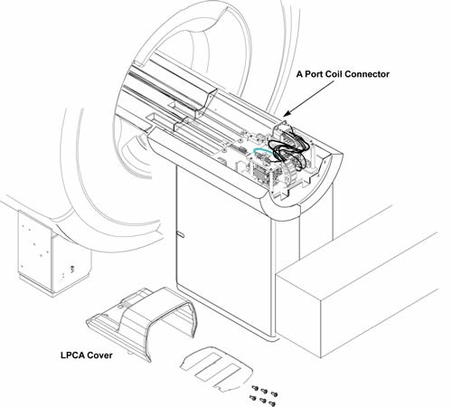
A Port Coil Connector Replacement
Prerequisites
Procedure
- Remove LPCA Cover. Refer to LPCA Cover Removal.
Figure 1. A Port Coil Connector
- Cut the 4 tie wraps fixing cables.
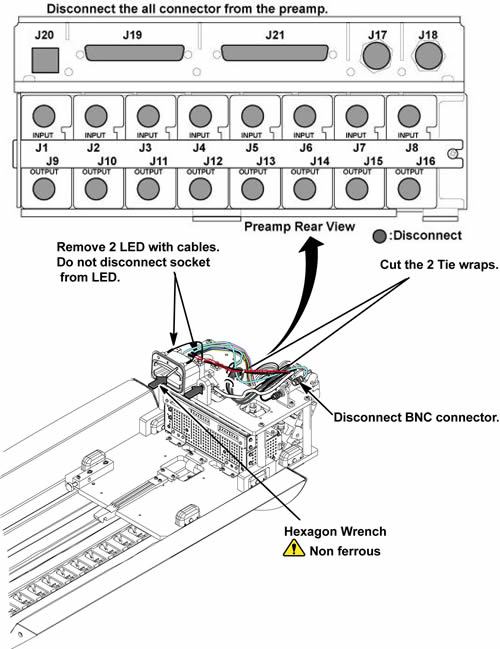
- Remove the following connectors. (BNC, J17 BNC, Sub-D Connector
J19, J20, J1 – J8 BNC connectors from MC pre-amp (Input Side) and
2 LED cable-With LED).
Figure 2. connectors
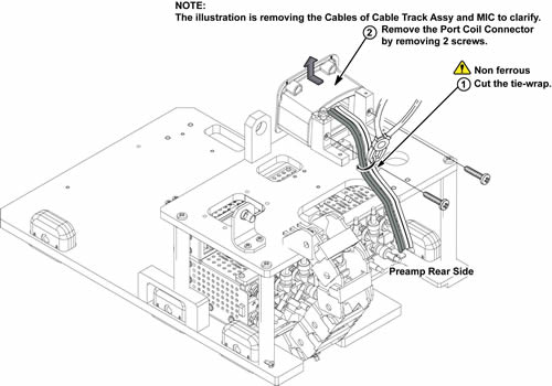
- Cut the tie wrap fixing coil port cables.
- Remove 2 screws from A Port Coil Connector assy.
- Remove A Port Coil Connector assy from the L brackets.
Figure 3. Remove A Port Coil Connector
- Install new A Port Coil Connector assy to the L brackets with 2 screws.
- notice
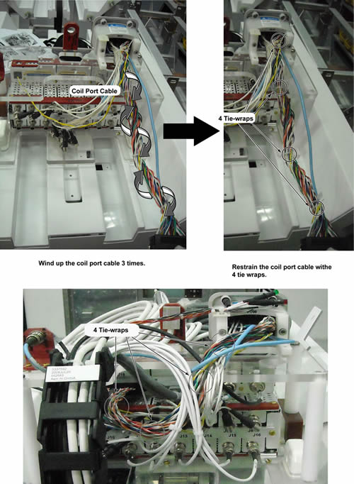
- Wind up the coil port cables of J19 connector three times.
- Restrain the coil port cable with 4 tie-wraps.
Figure 4. Installation of coil port cable (J19 connector)
- Connect the all connectors to the preamplifier and BNC.
- Restore new A Port Coil Connector assy by the reverse order of the removal.
 |
Finalization
- Restore the Power. Refer to Lockout / Tagout for System Cabinet PDU Main Breaker.
- Run MCR tool.
- Run one head or body scan.